background image

8

307–920

ADVERTENCIA

EL  ROCIADO a ALTA PRESIÓN PUEDE CAUSAR GRAVES LESIONES.

SOLO PARA USO PROFESIONAL. RESPETE LOS AVISOS DE ADVERTENCIA. 

Lea y entienda todo el manual de instrucciónes antes de manejar el equipo.

PELIGRO DE INYECCIÓN DE FLUIDO

Seguridad general

Este equipo genera un fluido a una presión muy alta. El rociado

de la pistola, los escapes de fluido o roturas de los com-

ponentes pueden inyectar fluido en la piel y el cuerpo y causar

lesiones extremadamente graves, incluyendo a veces la

necesidad de amputación. También, el fluido inyectado o sal-

picado en los ojos puede causar graves daños.
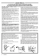
NUNCA apuntar la pistola hacia alguien o alguna parte del

cuerpo. NUNCA colocar la mano o los dedos encima de la bo–

quilla. NUNCA tratar de “hacer retornar la pintura”; este NO es

un sistema de rociado de aire.
SIEMPRE tener colocado el protector de la boquilla en la pis-

tolamientras se está pulverizando.
SIEMPRE seguir el procedimiento de descarga de presión,

dado másabjo, antes de limpiar o sacar la boquilla o de dar ser-

vicioa cualiquier equipo del sistema.
NUNCA tratar de parar o desviar los escapes con la mano o el

cuerpo.
Asegurar que todos los aparatos de seguridad del equipo están

funciónando bien antes de cada uso.

Tratamiento médico

Si pareciera que un poco de fluido penetró la piel, conseguir

TRATAMIENTO médico DE URGENCIA DE INMEDIATO. NO

TRATAR LA HERIDA COMO  UN SIMPLE CORTE.

 Decir al

médico exactamente cua fluido fue.
Aviso al médico: Si se llega a inyectar este fluido en la piel se

causa una lesión traumática.

 Es importante tratar quirúrgica-

mente la lesión a la brevedad posible.

 No demorar el

tratamiento para investigar la toxicidad. La toxicidad es algo de

suma importancia en algunas pinturas exóticas cuando se  in-

yectan directamente al torrente sanguineo. Sirá conveniente

consultar a un especialista en cirugia plástica o reconstructiva

de las manos.

Aparatos de seguridad de la pistola pulverizadora

Asegurar que todos los aparatos protectores de la pistola están

funciónando bien antes de cada uso. No sacar ni modificar

ningúna pieza de la pistola pues podria causar el malfuncióna-

miento de la misma con las consiguientes lesiones personales.
Pestillo de seguridad

Cada vez que se deje de pulverizar, aunque sea por un breve

momento, siempre colocar el pestillo de seguridad en la posi-

ción “cerrada” lo que deja la pistola inoperante. El no hacerlo

puede llevar al disparo imprevisto de la pistola.
Difusor

El difusor de la pistola dispersa el chorro pulverizado y reduce

el riesgo de inyección cuando no está instalada la boquilla.

Revisar con regularidad el funciónamiento del difusor. Seguir el

procedimiento de descarga de presión

, dado más abajo, y

después sacar la boquilla. Apuntar la pistola a un balde metáli-

co, sosteniéndola bien firme contra el. Utilizando la presión más

bajo posible, disparar la pistola. Si el fluido emitido no sale dis-

perso en un chorro irregular, reemplazar de inmediato el difusor.
Protector de la boquilla

SIEMPRE tener el protector de la boquilla colocado en la pistola

mientras se está pulverizando. Este protector llama la atención

contra el peligro de inyección y ayuda a reducir, pero no evita,

la colocación accidental de los dedos o cualquier otra parte del

cuerpo cerca de la boquilla.

Seguridad de la boquilla pulverizadora

Tener mucho cuidado al limpiar o cambiar las boquillas. Si llega-

ra a obstruirse mientras está pulverizando, enganchar el pes-

tillo de la pistola de inmediato. SIEMPRE seguir el 

pro–

cedimiento de descarga de presión

 y después sacar la bo–

quilla para limpiarla.
NUNCA limpiar la acumulación de pintura alrededor de la bo–

quilla antes de que se haya descargado por completo la presión

y el pestillo este enganchado.

1,5

2

4

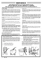
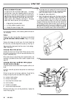
Procedimiento de descarga de presion

Para reducir el riesgo de sufrir graves lesiones corporales, in-

cluyendo inyeccion o lesiones causadas por piezas en

movimiento o choque electrico, siempre seguir este

procedimiento al apagar la maquina pulverizadora, al revisar

o dar servicio a cualquier parte del sistema de pulverizacion,

al instalar, limpiar o cambiar las boquillas, y cada vez que se

deja de pulverizar.

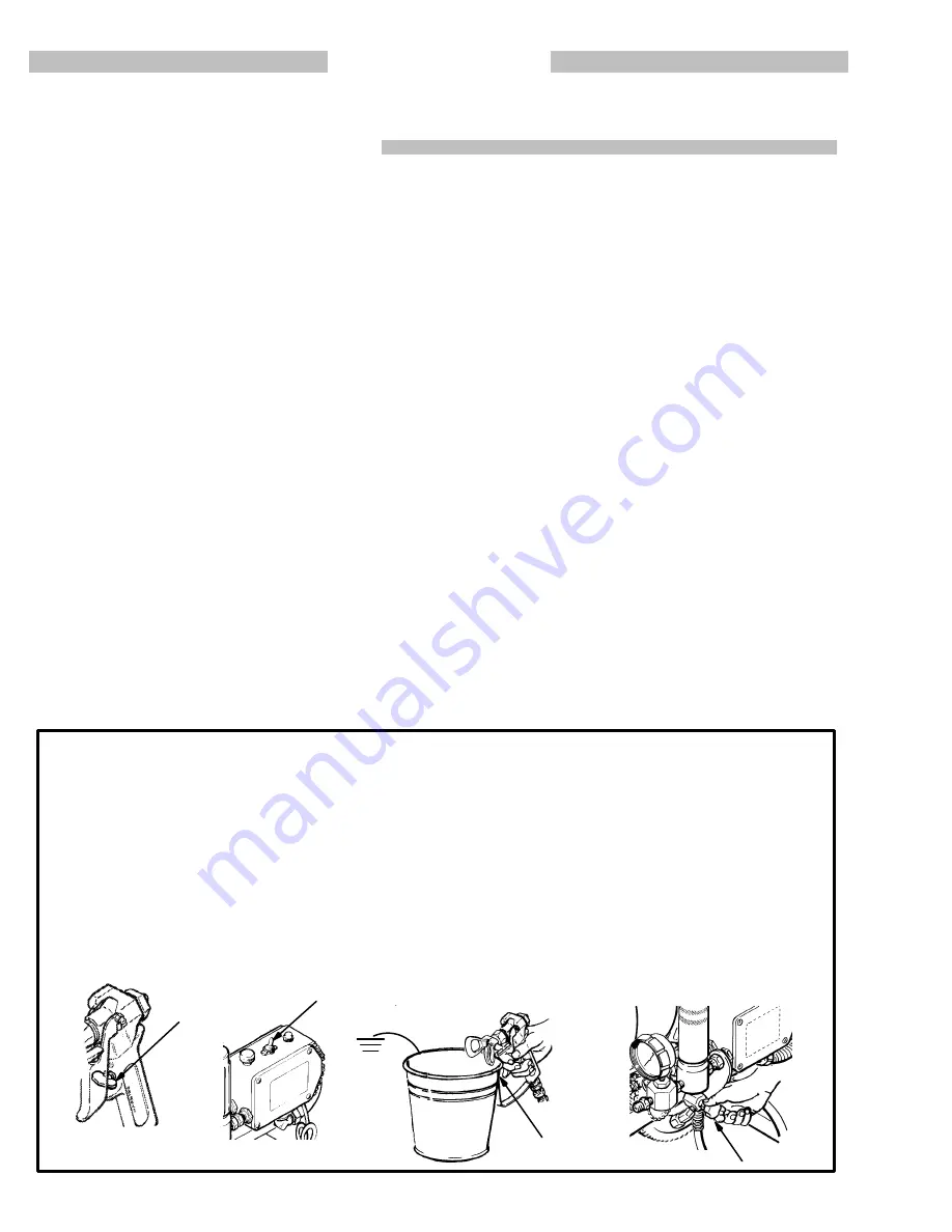
1. Enganchar el pestillo de la pistola.
2. Mover el interruptor electrico (ON/OFF) a la posicion

OFF (apagado).

3. Desenchufar el cordon electrico.

4. Desenganchar el pestillo de la pistola.  Sujetar una parte

metalica de la pistola bien firme contra un balde de

metal, y disparar la pistola para descargar la presion.

5. Enganchar el pestillo de la pistola.

6. Abrir la valvula de presion y tener listo un reclipiente para

recibir la pintura. Dejar la valvula de alivio de presion

abierta hasta que se este nuevamente listo para

pulverizar.

Si  se  sospecha  que la boquilla o la manguera esta com-

pletamente obstruida, o que no se ha descargado por com-

pleto la presion despues de haber seguido el procedimiento

anterior, aflojar MUY LENTAMENTE la tuerca de retencion del

protector de la boquilla o acoplamiento de la punta de la man-

guera y descargar gradualmente la presion, despues, aflojarlo

por completo. Luego, despejar la boquilla o la manguera.

6

Summary of Contents for 231-081

Page 1: ...88 GRACO INC Hazard of Using Fluids Containing Halogenated Hydrocarbons Never use 1 1 1 trichloroethane methylene chloride other halogenated hydrocarbon solvents or fluids containing such solvents in...

Page 2: ...ected pressure W orking together the pressure control and motor cause the pump to cycle whenever there is fluid or pressure demand When the pump is cycling the motor sounds like an automobile starter...

Page 3: ...3 307 920 DISPLACEMENT PUMP Fig 1 PRESSURE DRAIN VALVE DRIVE ASSEMBLY FLUID FILTER PRESSURE ADJUSTING KNOB MOTOR PRESSURE CONTROL RESET BUTTON ON OFF SWITCH TRIGGER SAFETY SHOWN ENGAGED...

Page 4: ...injection when the tip is not installed Check diffuser operation regularly Follow the Pressure Relief Procedure below then remove the spray tip Aim the gun into a metal pail holding the gun firmly to...

Page 5: ...l to maintaining a grounded spray system Check the electrical resistance of your fluid hoses at least once a week If your hose does not have a tag on it which specifies the maximum electrical resistan...

Page 6: ...er Le diffuseur du pistolet sert diviser le jet et r duire les risques d injection accidentelle quand l ajutage n est pas en place V rifier le fonctionnement du dif fuseur r guli rement Pour cette v r...

Page 7: ...aussi LES RISQUES D INCENDIE OU D EXPLOSI N ci dessus RISQUES D INCENDIE OU D EXPLOSI N De l lectricit statique est produite par le passage du fluide grande vitesse dans la pompe et dans les tuyaux S...

Page 8: ...la Difusor El difusor de la pistola dispersa el chorro pulverizado y reduce el riesgo de inyecci n cuando no est instalada la boquilla Revisar con regularidad el funci namiento del difusor Seguir el p...

Page 9: ...tes recomendados reemplazarla de inmediato Es muy ar riesgado tener una manguera sin puest a tierra o con la puest a tierra en malas condici nes Leer tambi n la informaci n sobre RIESGO DE INCENDIO O...

Page 10: ...e pressure control fitting to keep it from rotating Use an other wrench to tighten the mating fitting a Remove the cap from the filter outlet nipple and screw on a 50 ft 15 2 m minimum length main flu...

Page 11: ...OFF See Fig 4 Then plug the cord into a grounded electrical outlet at least 20 ft 6 m away from the spray area WARNING Proper electrical grounding is essential to reduce the risk of fire or explosion...

Page 12: ...way counterclockwise See Fig 4 5 Disengage the gun safety latch See Fig 7 6 To prime the pump hold a metal part of the gun firmly against and aimed into a metal waste con tainer See Fig 6 Squeeze the...

Page 13: ...sure Relief Proce dure Warning on page 12 2 If the spray tip clogs and you are using a RAC IV DripLess Tip Guard release the gun trigger en gage the gun safety latch and rotate the RAC IV handle 180 S...

Page 14: ...ing procedure 3 Lubricate the bearing housing after every 100 hours of operation Remove the front cover Fill the bearing housing cavity with SAE non detergent oil See Fig 7 4 Flush the sprayer at the...

Page 15: ...E FILTER BOWL SCREEN FILTER SUPPORT 3 Close the pressure drain valve 4 Put the suction tube in a grounded metal pail of com patible solvent 5 Remove the spray tip from the gun if it is installed WARNI...

Page 16: ...see if the motor starts 2 Relieve pressure refer to your separate gun or tip instruction manual for tip cleaning 1 Thaw Plug in sprayer and turn on Slowly in crease pressure setting to see if motor s...

Page 17: ...ing if broken Realign spring with brush See page 25 6 Clean brush holders Remove carbon with small cleaning brush Align brush leads with slot in brush holder to assure free verti cal brush movement 7...

Page 18: ...ace damaged terminals and recon nect securely 11 Replace circuit board See page 28 WHAT TO CHECK If check is OK go to the next check TYPE OF PROBLEM WHAT TO DO If check is not OK refer to this column...

Page 19: ...ood circuit board See page 28 13 Check motor armature for shorts by us ing an armature tester growler or per form spin test See page 22 14 Check bridge 308 by substituting with a good bridge or by per...

Page 20: ...f and unplug sprayer See page 33 1 Replace pin if missing Be sure retainer spring is fully in groove all around con necting rod See page 32 2 Replace connecting rod assembly See page 32 3 Check drive...

Page 21: ...a ture is determined to be good A bad armature will immediately burn out a good bridge 1 Repair or replace any damaged wir ing or terminals Securely reconnect all wires 2 Correct faulty conditions 3 R...

Page 22: ...to relieve pressure gradually then loosen completely Now clear the obstruction WARNING For checking armature motor winding and brush electri cal continuity Setup Remove the drive housing from the spr...

Page 23: ...each test and then check the continuity In Tests 1 2 and 3 there should be NO continuity In Tests 4 5 and 6 connect the and meter wires as indicated check continuity then switch the meter wire connec...

Page 24: ...rol malfunction be sure to properly mate connectors and never pull on a wire to disconnect it Pulling on a wire could loosen the connector from the wire 2 Route wires carefully in the pressure control...

Page 25: ...a new brush in the holder so the lead is in the long slot of the holder Slide the terminal under the terminal screw washer Make sure the motor lead is still connected the at the screw See Fig 14 7 Pl...

Page 26: ...ts or electric shock Unplug the sprayer WARNING Refer to Fig 16 except where noted 1 Remove the pressure control cover 2 Use a needle nose pliers to disconnect the upper ter minal wire from the micros...

Page 27: ...male connector is centered in the wrap around blade of the female connector when the connections are made Improper connections may cause the sprayer to malfunction Route all wires carefully to avoid i...

Page 28: ...close attention to where connections are made Refer to Fig 19 4 Pull out the black plastic tipped pin 86 Push the bottom of the circuit board toward the wall of the con trol and carefully slide the b...

Page 29: ...page 28 6 Remove the conduit 22 7 Remove the three screws 44 lockwashers 40 and nuts 41 located below the pressure control Remove the pressure control 8 Remove the screws 15 holding the back mounting...

Page 30: ...t is a 3000 psi 210 bar gauge and will be damaged if the system pressure is raised to 3800 psi 266 bar as required by this adjustment Use gauge 102 814 or the equivalent 1 Follow the Pressure Relief P...

Page 31: ...si 210 bar 17 Turn the pressure control knob to the minimum set ting Release the gun safety latch and trigger the gun into a grounded waste container until pressure is re lieved Engage the gun safety...

Page 32: ...aring and drive housings 10 Align the connecting rod with the crank E and care fully align the locating pins in the drive housing with the holes in the bearing housing 27 Push the bear ing housing ont...

Page 33: ...hers 65 from the upper rear of the motor end bell P 6 Tap the drive housing 18 with a plastic mallet to loosen it from the front end bell then pull it straight off DO NOT allow the gear cluster 9 to f...

Page 34: ...P Pull the drive hous ing away from the motor end bell DO NOT allow the gear cluster 9 to fall when re moving the drive housing 18 It is easily damaged if dropped The cluster may stay engaged in eithe...

Page 35: ...27 51 63 10 47 17 10 30 63 R 44 52 40 41 54 AC1 AC2 G1 G2 _ MOTOR LEADS DETAIL Shows position of conduit seal 5 in conduit connector 345 5 345 WIRING DIAGRAM WHITE BLUE YELLOW RED GREEN BLACK WHITE TH...

Page 36: ...ssembling the Pump 1 Unscrew the intake valve 224 from the cylinder 216 Remove the gasket 206 ball guide 215 stop pin 207 and ball 204 See Fig 27 2 Clean and inspect the parts for wear or damage re pl...

Page 37: ...n back off and tighten finger tight Fig 29 224 213 205 LIPS FACE DOWN 220 203 APPLY ONE DROP OF SEALANT TO THESE THREADS 217 LIPS FACE UP 223 6 Place the flats at the top of the rod in a vise 7 Use a...

Page 38: ...en end wrench and a light hammer See Fig 31 WARNING Be sure the retaining spring 35 is firmly in the groove of the connecting rod all the way around to prevent it from working loose due to vibration S...

Page 39: ...e carbon steel 1 212 183 232 GLAND female Delrinr 1 213 183 231 GLAND male Delrinr 1 214 178 945 NUT hex 1 215 178 948 GUIDE ball sst 1 216 183 234 CYLINDER stainless steel 1 217 178 964 V PACKING UHM...

Page 40: ...5 67 64 32 82 31 33 49 27 29 18 18b 10 10 18a 9 1 63 17 44 52 62 44 19 60 58 83 41 41 40 40 63 30 63 51 81 80 47 46 35 20 38 39 42 7 54 15 16 22 84 44 8 57 50 46 78 69 88 48 12 46 13 28 34 56 Model 23...

Page 41: ...4 33 107 210 CAPSCREW sch 3 8 16 unc 3a x 1 1 2 4 34 179 945 ADAPTER elbow special 1 4 18 npt m x f 1 35 176 817 SPRING retaining 1 36 183 995 COVER pressure control 1 38 178 941 NUT hex 1 39 222 341...

Page 42: ...107 260 TERMINAL FEMALE 1 320 107 266 TERMINAL FEMALE 1 321 103 885 TERMINAL MALE 1 322 103 886 TERMINAL FEMALE 3 323 107 265 TERMINAL FEMALE 1 324 107 263 TERMINAL FEMALE 1 325 102 799 TERMINAL RING...

Page 43: ...AGRAM AC1 AC2 G1 G2 _ WHITE BLUE YELLOW RED GREEN BLACK WHITE THERMAL SWITCH GROUND WIRE BLACK POWER SUPPLY CORD MOTOR 336 Ref 85 86 1a 323 320 302 317 318 316 324 306 303 309 312 321 1c 322 337 308 3...

Page 44: ...O PART NO DESCRIPTION QTY 1 101 818 CLAMP HOSE 1 2 160 327 UNION 90 swivel 3 4 npt m x f 1 3 170 705 ADAPTER intake 1 4 170 706 HOSE 1 id x 48 nylon 1 5 170 957 TUBE suction 1 6 181 072 STRAINER 1 1 3...

Page 45: ...Paint Filter 60 mesh 250 micron Stainless Steel Screen reusable Pump Inlet Size 3 4 npt m with 30 ID chamfer Fluid Outlet Size 1 4 npsm from fluid filter Wetted Parts Displacement Pump Stainless Steel...

Page 46: ...183 194 183 350 110 240 222 554 222 555 Cart Screw Ring Button Plug Sleeve Washer Clip Handle Cart OLD NEW 14 181 743 185 430 Shield Shield OLD 8 NEW 4 15 106 075 106 078 Screw Screw OLD NEW 16 179 93...

Page 47: ...47 307 920...

Page 48: ...Graco distributor for verification of the claim If the claimed defect is verified Graco will repair or replace free of charge any defective parts The equipment will be returned to the original purcha...

Reviews: