308620
30
Reassembly
6.
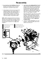
Be sure the face of the
rotor (51a)
and the clamp
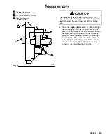
(55) are free of all burrs. Install the rotor, lock-
washers (16) and capscrews (57). Torque the
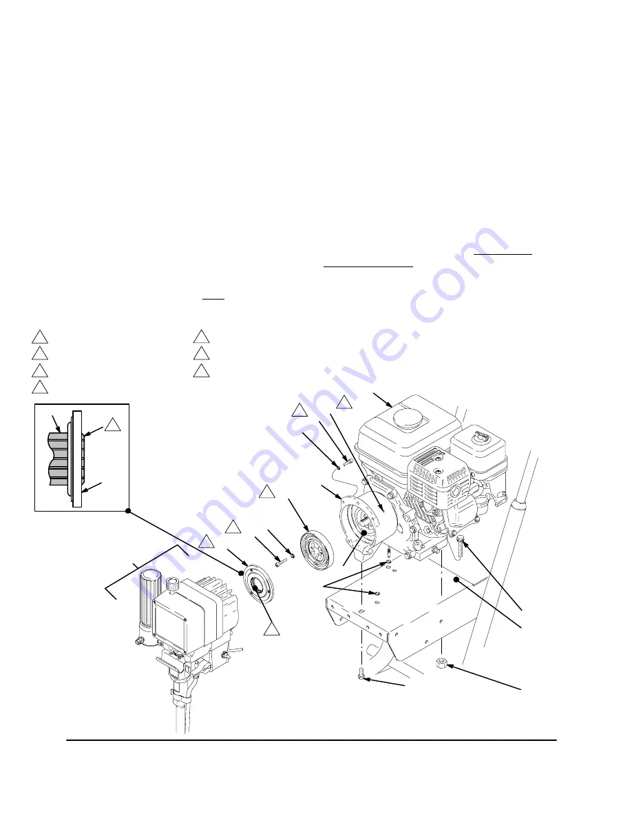
capscrews to 7 ft–lb (9.5 N.m). See Fig. 23.
7.
After installing the rotor (51a) the air gap must be
adjusted between the rotor and the field (53).
Tighten the setscrews (58) oppositely and evenly.
Pull the engine recoil rope to assure that the
engine turns freely, and there is no contact be-
tween the rotor and the field. If there is contact,
loosen the setscrews and reposition the field.
NOTE:
With the autogap style armature, the gap be-
tween the rotor and the armature is critical for proper
operation. The clutch kits with an autogap style arma-
ture include a cardboard spacer (p/n 186857) to set
the proper gap. This spacer is for use
only
during
installation.
8.
Clean the face of the
armature (51b)
. With the flat
side of the armature facing the rotor (51a), slide
the armature onto the hub (2h) in the drive/pinion
assembly (D) just until the chamfered end of the
hub (2h) protrudes through the armature. See
Detail B, Fig. 23. There will be significant resis-
tance. Attach the cardboard spacer, supplied with
the clutch kit, to the face of the armature. Bend
tabs over outside diameter of armature.
Brace the cart against a wall to keep it from rolling.
Push the drive/pinion assembly onto the clutch
housing (1). There will be significant resistance.
When the mating surfaces of the drive/pinion as-
sembly and the clutch housing (1) are flush, re-
move the drive/pinion assembly.
Remove the
cardboard spacer.
9.
Assemble the
drive assembly (D)
to the clutch
housing (1), using the capscrews (59) and lock-
washers (16). See Fig. 23.
05843C
05843B
Fig. 23
A
78
61
51b
16
51a
53
1
48
57
58
77
16
59
1
3
4
2
Torque the screw to 7 ft–lb (9.5 N.m).
The face must be clean.
1
2
Spline
4
2
To engine alternator.
Detail B
5
52
2h
D
50
Chamfered end of hub (2h)
5
06007
6
Apply low strength thread locker.
7
Torque to 100 in.-lb (N
m).
7
6


