background image

Installation 

6

311001C

Installation

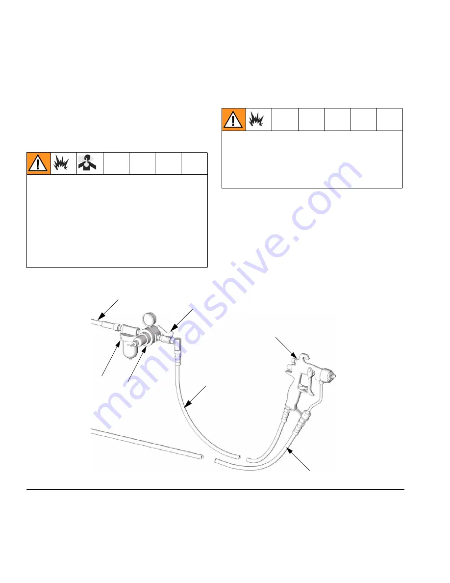
Typical Installation

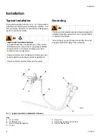
The typical installation shown in F

IG

. 1 is only a guide for 

selecting and installing air-assisted spray systems. Con-
tact your Graco distributor for assistance in designing a 
system to meet your needs.

Grounding

Key:

A

Air Line Filter

B

Air Shutoff Valve

C

Gun Air Pressure Regulator 

D

Air  Line

E

Spray  Gun

F

Electrically Conductive Fluid Hose

G

Gun Air Supply Hose

VENTILATE THE SPRAY BOOTH

To prevent hazardous concentrations of toxic and/or 
flammable vapors, spray only in a properly ventilated 
spray booth. Do not operate the spray gun unless 
ventilation fans are operating.

Check and follow all of the National, State, and Local 
codes regarding air exhaust velocity requirements.

Check and follow all local safety and fire codes.

Check your local electrical code and pump manual for 
detailed grounding instructions. Use only electrically 
conductive fluid hoses.

Ground the spray gun through connection to a prop-
erly grounded fluid supply hose and pump.

F

IG

. 1: Typical Installation (Model G15 Shown)

TI6554A

A

B

C

E

F

G

D

Summary of Contents for 249233

Page 1: ...ions Parts List AA Series Spray Gun For air assisted spraying and finishing of paints and coatings Important Safety Instructions Read all warnings and instructions in this manual Save these instructions See page 2 for List of Models and Table of Contents Model G15 TI6553A Model G40 TI6844A TI7204B Model G40 w RAC tip II 2 G ...

Page 2: ...pair 22 Fluid Tube Replacement 22 Reassembly 24 Parts 26 Spray Tip Selection Chart 30 AAM Fine Finish Spray Tips 30 GG4 Industrial Spray Tips 30 LTX RAC Spray Tips 31 FFT Fine Finish RAC Spray Tips 32 WRX WideRAC Spray Tips 32 Accessories 33 Technical Data 34 Dimensions 35 Graco Standard Warranty 36 Graco Information 36 Models Part No Series Maximum Working Air Pressure psi MPa bar Maximum Working...

Page 3: ...le in the following languages Manual Language 311001 English 311145 Chinese 311146 Danish 311147 Dutch 311148 Finnish 311149 French 311150 German 311151 Italian 311152 Japanese 311153 Korean 311154 Norwegian 311155 Polish 311156 Russian 311157 Spanish 311158 Swedish ...

Page 4: ...look like just a cut but it is a serious injury that can result in amputation Get immediate surgical treatment Do not point gun at anyone or at any part of the body Do not put your hand over the spray tip Do not stop or deflect leaks with your hand body glove or rag Do not spray without tip guard and trigger guard installed Engage trigger lock when not spraying Follow Pressure Relief Procedure in ...

Page 5: ... eyes or on skin inhaled or swallowed Read MSDS s to know the specific hazards of the fluids you are using Store hazardous fluid in approved containers and dispose of it according to applicable guidelines PERSONAL PROTECTIVE EQUIPMENT You must wear appropriate protective equipment when operating servicing or when in the operating area of the equipment to help protect you from serious injury includ...

Page 6: ... SPRAY BOOTH To prevent hazardous concentrations of toxic and or flammable vapors spray only in a properly ventilated spray booth Do not operate the spray gun unless ventilation fans are operating Check and follow all of the National State and Local codes regarding air exhaust velocity requirements Check and follow all local safety and fire codes Check your local electrical code and pump manual fo...

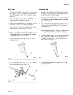
Page 7: ...ow it out with air and flush it with solvent Use solvent which is com patible with the fluid to be sprayed If better control of fluid pressure is needed install a fluid regulator on the fluid line to better control fluid pressure to the gun 1 Use a fluid filter to remove coarse particles and sed iment to avoid clogging the spray tip and causing finishing defects 2 Connect the fluid hose F to the g...

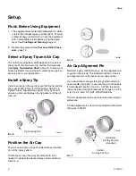
Page 8: ...ing ring 6 firmly by hand to ensure a good seal between the tip gasket and the dif fuser 5 Position the Air Cap The air cap and spray tip position determines the direc tion of the spray pattern Rotate the air cap the spray tip rotates with it as needed to achieve the desired spray pattern direction See FIG 6 Air Cap Alignment Pin Model G15 guns 249233 use an air cap alignment pin to position the a...

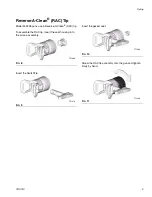
Page 9: ...Reverse A Clean RAC tip To assemble the RAC tip insert the seat housing into the air cap assembly Insert the SwitchTip Insert the gasket seat Screw the RAC tip assembly onto the gun and tighten firmly by hand FIG 8 FIG 9 TI7196A TI7197A FIG 10 FIG 11 TI7198A TI7199A ...

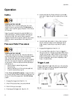
Page 10: ... or bumped SKIN INJECTION HAZARD Remember this is not an air spray gun For your safety be sure to read and follow the Warnings on pages 4 and 5 and throughout the text of this instruc tion manual Keep the wallet sized warning card 222385 pro vided with the gun with the operator of this equip ment at all times The card contains important treatment information should an injection injury occur Additi...

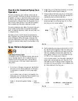
Page 11: ...pressure is controlled by the air regulator sup plying the pump per the formula below 2 Trigger the gun to check the atomization do not be concerned about the pattern shape yet 3 Slowly increase the fluid pressure just to the point where a further increase in fluid pressure does not significantly improve fluid atomization 4 Close off the pattern adjustment air by turning the knob clockwise in all ...

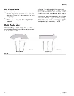
Page 12: ... consistent distance of approximately 8 to 12 in 200 to 300 mm from the object being sprayed 2 To obtain an even finish use smooth even strokes across the object being sprayed with 50 overlap 3 Paint using parallel strokes This spray gun applies all coatings evenly without cross coating For HVLP operation the atomization air must not exceed 10 psi Use HVLP Verification Kit 249140 to verify air psi...

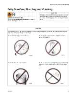
Page 13: ...it will damage aluminum and nylon compo nents CAUTION Solvent left in gun air passages could result in a poor quality paint finish Do not use any cleaning method which may allow solvent into the gun air passages Do not point the gun up while cleaning it Do not immerse the gun in solvent Do not wipe the gun with a cloth soaked in solvent wring out the excess Do not use metal tools to clean the air ...

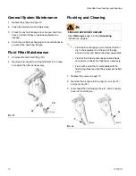
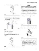
Page 14: ...he filter as necessary Flushing and Cleaning 1 Relieve the pressure page 10 2 Remove the air cap retaining ring 6 air cap 21 and spray tip 33 3 Disconnect the fluid supply hose F and air supply hose G from the gun FIG 17 TI6735A 12 18 FIRE AND EXPLOSION HAZARD Read Warnings page 4 Follow Grounding instructions page 6 Flush before changing colors before fluid can dry in the equipment at the end of ...

Page 15: ...sly soak the brush s bris tles with solvent and do not use a wire brush 11 With the gun pointed down clean the front of the gun using the soft bristle brush and solvent 12 Scrub the air cap retaining ring 6 air cap 21 dif fuser 5 and spray tip 33 with the soft bristle brush To clean out air cap holes use a soft tool such as a toothpick to avoid damaging critical sur faces Blow air through the spra...

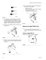
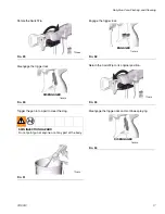
Page 16: ...th solvent and wring out the excess Point the gun down and wipe off the outside of the gun 16 After cleaning the gun lubricate the following parts with lubricant 111265 weekly Trigger pivot pin A Boss on both sides of the gun where the trigger contacts the gun body B Fluid needle shaft behind trigger C Reverse A Clean RAC Tip Clearing a clogged RAC tip Release the trigger and engage the trigger lo...

Page 17: ...clear the clog Engage the trigger lock Return the SwitchTip to its original position Disengage the trigger lock and continue spraying FIG 29 FIG 30 SKIN INJECTION HAZARD Do not point gun at anyone or at any part of the body FIG 31 TI7200A TI6582A DISENGAGED TI7202A FIG 32 FIG 33 FIG 34 TI6581A ENGAGED TI7201A TI6582A DISENGAGED ...

Page 18: ...st be replaced whenever the seat assembly is removed Fluid viscosity too low for proper seal with carbide seat Install acetal seat 5c Fluid in air passages Spray tip seal leaking Tighten retaining ring 6 or replace spray tip 33 Leaking around seat housing Replace the gasket 5b model G40 gun only The gasket must be replaced whenever the seat assembly is removed Fluid inlet fitting leaking Replace t...

Page 19: ...g in poor atomization and or spitting Striping spray Spray tip partially plugged Clean or replace spray tip See page 14 Irregular pattern Fluid build up on spray tip or spray tip partially plugged Clean or replace spray tip See page 14 On defective side of pattern air horn holes are partially or totally plugged Clean air horn holes with solvent and soft brush See page 14 Pattern pushed to one side...

Page 20: ...he pressure page 10 Remove the fluid and air hoses from the gun 2 Remove the air cap retaining ring 6 air cap 21 and spray tip 33 See FIG 36 3 Trigger the gun to pull the needle housing off the seat while you unscrew the diffuser 5 from the gun body 1 using the gun tool 30 Seal Repair Kit 249422 is available For best results use all the new parts in the kit Kit parts are marked with an asterisk fo...

Page 21: ... Remove the trigger pivot pin nut 14 pivot pin 13 and trigger 3 using the gun tool 30 and nut driver 29 See FIG 38 3 Remove the fluid needle assembly 2 from the front of the gun by using the nut driver tool 29 If the needle is bent or damaged or the packing is worn or leaking replace the entire needle assembly If replacement is necessary be sure to remove the o ring 2a as it may stick inside the g...

Page 22: ... the u cup is worn or leaking carefully remove the u cup from the front of the gun body using a pick Fluid Tube Replacement 1 Remove the air inlet fitting 17 using the gun tool 30 and remove the screw 20 using a 3 16 in hex wrench 2 Unscrew the fluid inlet fitting 18 Remove and clean or replace the inline fluid filter 12 3 Unscrew the fluid tube connector C from the gun s fluid inlet Carefully rem...

Page 23: ...Repair 311001C 23 ...
Page 24: ...t the shaft 9 and seat 10 in the air valve 8 6 Install the two springs 15 and 19 Screw the spring cap 11 into the back of the gun body Torque to 175 185 in lb 20 21 N m 7 Lightly lubricate the needle assembly o rings and shaft where the packing slides Be sure that the o ring 2a is in place in the gun body 1 8 Insert the fluid needle assembly 2 into the front of the gun Use the nut driver 29 to scr...

Page 25: ...18 19 N m Torque to 20 30 in lb 2 3 N m Do not lubricate diffuser o rings Brass part must be behind trigger Lips face out of gun body Torque to 50 60 in lb 6 7 N m Torque to 125 135 in lb 14 15 N m Torque to 45 50 in lb 5 6 N m Use low strength thread locker Torque to 175 185 in lb 20 21 N m 1 3 4 5 6 7 8 9 10 11 12 13 21a G15 only 12 12 16 249233 249242 only 249238 249233 249242 only 249233 24924...

Page 26: ...Gun Part No 249246 G40 Gun High Flow 1 2 3 4 5a 6 G15 only 7 8 9 10 11 13 14 15 17 19 21 22 33 6b 5e 5f 5g 5b G40 only 5c 5d 2a TI6579A 1a 6 G40 only 6a 21a G15 only TI6579B 29 30 28 12 16 18 20 16 249233 249242 only 249246 only 249233 249242 only 249233 249242 only ...

Page 27: ... 1 12 224453 FILTER tip pkg of 5 1 13 PIN pivot 1 14 PIN pivot nut 1 15 114069 SPRING compression 1 16 249136 TUBE assy 1 17 15F202 FITTING air inlet 1 18 15F186 FITTING hose 1 19 119767 SPRING compression 249233 only 1 115141 SPRING compression 287926 only 1 20 119996 SCREW cap socket hd 1 4 20 x 3 8 in 10 mm 1 21 249596 AIR CAP includes item 21a 1 21a 15G618 PIN air cap indexing 1 22 GASKET tube...

Page 28: ...Parts 28 311001C Parts Part No 249238 G40 Gun w RAC Tip 1 2 3 4 5a 7 8 9 10 11 13 14 15 16 17 19 20 22 5f 5g 5b 2a 1a TI7203B 29 30 28 33a 35 6 33 6a 5c 5d ...

Page 29: ...ng 1 5b GASKET seat nylon 1 5c SEAT carbide 1 5d NUT seat 1 5e PACKING o ring seat PTFE 1 5f PACKING o ring PTFE 1 5g PACKING o ring PTFE 1 6 249478 TIP GUARD AIR CAP ASSY 1 6a PACKING o ring PTFE 1 7 PACKING u cup UHMWPE 1 8 VALVE air assy 1 9 15F193 SHAFT fluid spring 1 10 15F194 SEAT spring 1 11 15F195 CAP spring 1 13 PIN pivot 1 14 PIN pivot nut 1 15 114069 SPRING compression 1 16 249317 TUBE ...

Page 30: ...fl oz min lpm Maximum Pattern Width at 12 in 305 mm at 600 psi 4 1 MPa 41 bar at 1000 psi 7 0 MPa 70 bar 2 to 4 100 4 to 6 150 6 to 8 200 8 to 10 250 10 to 12 300 12 to 14 350 14 to 16 400 16 to 18 450 18 to 20 500 0 007 0 178 4 0 0 1 5 2 0 15 107 207 307 0 009 0 229 7 0 0 2 9 1 0 27 109 209 309 409 509 0 011 0 279 10 0 0 3 13 0 0 4 111 211 311 411 511 611 0 013 0 330 13 0 0 4 16 9 0 5 213 313 413...

Page 31: ... mm at 2000 psi 14 0 MPa 140 bar 2 to 4 100 4 to 6 150 6 to 8 200 8 to 10 250 10 to 12 300 12 to 14 350 14 to 16 400 16 to 18 450 18 to 20 500 0 009 0 229 11 2 0 33 209 309 0 011 0 279 16 6 0 49 211 311 411 511 0 013 0 330 23 3 0 69 213 313 413 513 0 015 0 381 30 8 0 91 215 315 415 515 615 0 017 0 432 39 5 1 17 217 317 417 517 617 0 019 0 483 49 7 1 47 219 319 419 519 619 0 021 0 533 60 5 1 79 321...

Page 32: ...Pa 140 bar 4 to 6 150 6 to 8 200 8 to 10 250 10 to 12 300 12 to 14 350 0 008 0 203 8 8 0 26 208 308 0 010 0 254 13 9 0 41 210 310 410 510 0 012 0 305 19 9 0 59 212 312 412 512 612 0 014 0 356 27 0 0 80 214 314 414 514 614 Orifice Size in mm Fluid Output fl oz min lpm Maximum Pattern Width at 12 in 305 mm at 2000 psi 14 0 MPa 140 bar 24 in 610 0 021 0 533 60 5 1 79 1221 0 023 0 584 72 7 2 15 1223 0...

Page 33: ... Ball Valve 238694 5000 psi 35 MPa 350 bar Maximum Working Pressure 3 8 npt mbe SST wetted parts PEEK seats PTFE seals Compatible with acid catalyzed materials Can be used as fluid drain valve HVLP Verification Kit 249140 Use to check air cap air pressure at various air supply air pressures Do not use for actual spraying RAC Gasket 246453 Pack of five standard replacement RAC gaskets item 33a Acet...

Page 34: ...14 psi 0 098 MPa 0 98 bar Maximum Working Fluid Temperature 110 F 43 C Fluid Inlet 1 4 18 npsm Air Inlet 1 4 18 npsm R1 4 19 compound male thread Gun Weight 16 oz 450 grams Sound Pressure at 20 psi 140 kPa 1 4 bar 66 9 dB A Sound Pressure at 100 psi 0 7 kPa 7 bar 80 0 dB A Sound Power at 20 psi 140 kPa 1 4 bar 76 8 dB A Sound Power at 100 psi 0 7 kPa 7 bar 89 9 dB A Wetted Parts Stainless Steel Ca...

Page 35: ...Dimensions 311001C 35 Dimensions 6 1 in 15 5 cm 8 0 in 20 3 cm 6 9 in 17 5 cm 5 0 in 12 7 cm Model G15 TI6583A 6 9 in 17 5 cm 5 8 in 14 7 cm 8 0 in 20 3 cm 6 9 in 17 5 cm Model G40 TI6845A ...

Page 36: ...kmanship repairs will be made at a reasonable charge which charges may include the costs of parts labor and transportation THIS WARRANTY IS EXCLUSIVE AND IS IN LIEU OF ANY OTHER WARRANTIES EXPRESS OR IMPLIED INCLUDING BUT NOT LIMITED TO WARRANTY OF MERCHANTABILITY OR WARRANTY OF FITNESS FOR A PARTICULAR PURPOSE Graco s sole obligation and buyer s sole remedy for any breach of warranty shall be as ...

Reviews: