background image

Setup 

8

3A0149C

Setup

Flush Before Using Equipment

1.

The equipment was tested with lightweight oil, which 
is left in the fluid passages to protect parts. To avoid 
contaminating your fluid with oil, flush the equipment 
with a compatible solvent before using the equip-
ment. See Flushing and Cleaning, page 14.

2.

Relieve the pressure. See Pressure Relief Proce-
dure
, page 10.

Select a Spray Tip

The fluid flow and pattern width depend on the size of 
the spray tip, the fluid viscosity, and the fluid pressure. 
See Spray Tip Selection Chart, page 32. Contact your 
Graco distributor for assistance in selecting an appropri-
ate spray tip for your application.

Air Cap Alignment Pin

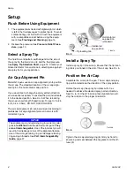
Model G15 guns use an air cap alignment pin to position 
the air cap. The standard location of the air cap align-
ment pin is the horizontal air cap position.

If you would like to change the spray pattern direction, 
use a needle nose pliers to unscrew the pin and relocate 
it to the desired position. See F

IG

. 5. When relocating 

the pin use low-strength thread locker. Torque to 1.5-2.5 
in-lb (0.2-0.3 N•m). DO NOT OVERTIGHTEN.

The air cap alignment pin can be removed according to 
preference. Air cap alignment pins will not work with 
model G40 guns.

Install a Spray Tip

Install a spray tip in the air cap. Ensure that the tip locat-
ing tab is positioned in the slot of the air cap. See F

IG

. 5. 

Position the Air Cap

Assemble the air cap to the gun. The air cap and spray 
tip position determine the direction of the spray pattern. 

Rotate the air cap (the spray tip rotates with it) as 
needed to achieve the desired spray pattern direction. 
See F

IG

. 6. For the G15 air cap, the alignment pin will 

stop the rotation in the proper orientation.

Tighten the air cap retaining ring (6) firmly by hand to 
ensure a good seal between the tip gasket and the dif-
fuser (5).

NOTICE

The alignment pin and retaining ring for current model 
guns are different from the earlier model guns. They 
are not interchangeable.
 Use of the incorrect pin will 
result in fluid leakage or loss of the alignment feature. 
Use of the wrong retaining ring will damage retaining 
ring and gun threads. See Part Interchangeability 
Guide
, page 37.

F

IG

. 5

F

IG

. 6

TI6847A

Slot

Tip locating tab

Horizontal air 
cap position 
(standard)

Vertical air 
cap position

TI6558A

Summary of Contents for 24C853

Page 1: ...particularly in applications requiring uniform atomization and high transfer efficiency For professional use only Important Safety Instructions Read all warnings and instructions in this manual Save...

Page 2: ...Spray Tips for use with G15 G40 Air Cap 32 RAC SwitchTips for use with G40 RAC Air Cap 33 RAC SwitchTips for use with G40 RAC Air Cap Continued 34 Accessories 35 Part Interchangeability Guide 37 Dimen...

Page 3: ...elated Manuals 3A0149C 3 Related Manuals This manual is available in the following languages Manual Language 3A0149A English 3A0283A French 3A0282A Spanish 3A0442 Chinese 3A0443 Japanese 3A0444 Korean...

Page 4: ...when flammable fumes are present Ground all equipment in the work area See Grounding instructions Use only grounded hoses Hold gun firmly to side of grounded pail when triggering into pail If there i...

Page 5: ...t Use equipment only for its intended purpose Call your distributor for information Route hoses and cables away from traffic areas sharp edges moving parts and hot surfaces Do not kink or over bend ho...

Page 6: ...ir Supply Hose To prevent hazardous concentrations of toxic and or flammable vapors spray only in a properly ventilated spray booth Do not operate the spray gun unless ventilation fans are operating C...

Page 7: ...he air hose G to the out let of the air shutoff valve See FIG 3 Fluid Line Before connecting the fluid line blow it out with air and flush it with solvent See Flushing and Clean ing page 14 Use solven...

Page 8: ...orque to 1 5 2 5 in lb 0 2 0 3 N m DO NOT OVERTIGHTEN The air cap alignment pin can be removed according to preference Air cap alignment pins will not work with model G40 guns Install a Spray Tip Inst...

Page 9: ...t seat Screw the RAC tip assembly onto the gun and tighten firmly by hand FIG 7 FIG 8 FIG 9 TI7196A TI7197A TI7198A FIG 10 NOTICE The RAC assembly for current model guns uses a different seat housing...

Page 10: ...the gun air supply 4 Disengage the trigger lock See FIG 12 5 Hold a metal part of the gun firmly to a grounded metal pail Trigger the gun to relieve pressure See FIG 11 6 Open all fluid drain valves...

Page 11: ...tomization do not be concerned about the pattern shape yet 3 Slowly increase the fluid pressure just to the point where a further increase in fluid pressure does not significantly improve fluid atomiz...

Page 12: ...arc with the gun as it causes an uneven coat of fluid See FIG 15 1 To achieve the best results when applying fluid keep the gun perpendicular to the surface and main tain a consistent distance of app...

Page 13: ...TICE Do not use any cleaning method which may allow solvent into the gun air passages Solvent left in gun air pas sages could result in a poor quality paint finish Do not point the gun up while cleani...

Page 14: ...f the day before storing and before repairing equipment Flush at the lowest pressure possible Check con nectors for leaks and tighten as necessary Flush with a fluid that is compatible with the fluid...

Page 15: ...sh s bris tles with solvent and do not use a wire brush 11 With the gun pointed down clean the front of the gun using the soft bristle brush and solvent 12 Scrub the air cap retaining ring 6 air cap 2...

Page 16: ...olvent and wring out the excess Point the gun down and wipe off the outside of the gun 16 After cleaning the gun lubricate the following parts with lubricant 111265 weekly Trigger pivot pin A Boss on...

Page 17: ...a pail to clear the clog Engage the trigger lock Return the SwitchTip to its original position Disengage the trigger lock and continue spraying FIG 28 FIG 29 Do not point gun at anyone or at any part...

Page 18: ...un only if it is worn The seat must be replaced it if is worn Fluid viscosity too low for proper seal with carbide seat Install plastic seat 5c Fluid in air passages Spray tip seal leaking Tighten ret...

Page 19: ...r replace spray tip See page 14 Irregular pattern Fluid build up on spray tip or spray tip partially plugged Clean or replace spray tip See page 14 On defective side of pattern air horn holes are part...

Page 20: ...ise to prevent damage to the seat 5c Install the replacement fan valve assem bly into the gun body 1 Screw the packing nut A into the gun body and torque to 90 in lb 10 5 N m Complete Gun Packing Repa...

Page 21: ...n The seat must be replaced if it is worn Needle Repair 1 Remove the diffuser see Seat Repair page 20 2 Remove the trigger pivot pin nut 14 pivot pin 13 and trigger 3 using the gun tool 30 and nut dri...

Page 22: ...e u cup is worn or leaking carefully remove the u cup from the front of the gun body using a pick Fluid Tube Replacement 1 Remove the air inlet fitting 17 using the gun tool 30 and remove the screw 20...

Page 23: ...Repair 3A0149C 23...

Page 24: ...o the air valve 8 6 Install the two springs 15 and 19 Screw the spring cap 11 into the back of the gun body Torque to 210 220 in lb 24 25 N m 7 Lightly lubricate the needle assembly o rings and shaft...

Page 25: ...n lb 18 19 N m Torque to 20 30 in lb 2 3 N m Do not lubricate diffuser o rings Brass part must be behind trigger Lips face out of gun body Torque to 50 60 in lb 6 7 N m Torque to 210 220 in lb 24 25 N...

Page 26: ...C856 G40 Gun High Flow 1 2 3 4 5a 6 G15 only 7 8 9 11 13 14 15 17 19 21 22 33 6b 5e 5f 5g 5b carbide only 5c 5d 2a 1a 6 G40 only 6a 21a G15 only TI6579D 29 30 28 12 16 18 20 16 24C856 only 24C853 24C8...

Page 27: ...c SEAT plastic 24C854 only 1 5c SEAT carbide 24C853 only 1 5d NUT seat 1 5e 111116 PACKING o ring seat PTFE 1 5f 109450 PACKING o ring PTFE 1 5g 111457 PACKING o ring PTFE 1 6 24D438 RING retaining in...

Page 28: ...0 PACKING o ring PTFE 1 5g 111457 PACKING o ring PTFE 1 6 24D439 TIP GUARD includes items 6a and 6b 24C855 24C856 only 1 6a 109213 PACKING o ring PTFE 2 6b 15G320 WASHER PTFE 1 7 188493 PACKING u cup...

Page 29: ...Parts 3A0149C 29...

Page 30: ...Parts 30 3A0149C Part No 24C857 G40 Gun with RAC Tip 1 2 3 4 5a 7 8 9 11 13 14 15 16 17 19 20 22 5f 5g 5b 2a 1a TI7203B 29 30 28 33a 35 6 33 6a 5c 5d TI6580A...

Page 31: ...5d NUT seat 1 5e 111116 PACKING o ring seat PTFE 1 5f 109450 PACKING o ring PTFE 1 5g 111457 PACKING o ring PTFE 1 6 24C921 TIP GUARD AIR CAP ASSY includes item 35 1 6a 109213 PACKING o ring PTFE 1 7...

Page 32: ...he skin Orifice Size in mm Fluid Output fl oz min lpm Maximum Pattern Width at 12 in 305 mm in mm at 600 psi 4 1 MPa 41 bar at 1000 psi 7 0 MPa 70 bar 2 to 4 100 4 to 6 150 6 to 8 200 8 to 10 250 10 t...

Page 33: ...47 312 412 512 612 0 015 0 381 16 0 0 47 21 0 0 62 414 514 614 0 017 0 432 20 0 0 59 26 5 0 78 416 516 616 Fluid output Q at other pressures P can be calculated by this formula Q 0 041 QT where QT flu...

Page 34: ...th at 12 in 305 mm in mm 4 to 6 150 6 to 8 200 8 to 10 250 10 to 12 300 12 to 14 350 Spray Tip 0 008 0 203 8 8 0 26 208 308 0 010 0 254 13 9 0 41 210 310 410 510 0 012 0 305 19 9 0 59 212 312 412 512...

Page 35: ...e gun G15 Gun Flush Box Insert 15G093 Insert for use with Gun Flush Box 244105 and G15 Spray Guns G40 Gun Flush Box Insert 15G346 Insert for use with Gun Flush Box 244105 and G40 Spray Guns Gun Lubric...

Page 36: ...ts qty of ten for Model G40 guns and G15 guns with a carbide seat Tip Filter Kit 241804 Replacement filters for spray tip orifice sizes 0 007 0 009 and 0 011 Quantity of 10 Trigger Repair Kit 249585 K...

Page 37: ...49256 No See note below table RAC seat housing 15F442 15J770 No Works properly only with RAC Tip Guard Air Cap Assembly 24C921 and is included in that kit Seat will fit into older model assemblies but...

Page 38: ...Dimensions 38 3A0149C Dimensions 6 1 in 15 5 cm 8 0 in 20 3 cm 6 9 in 17 5 cm 5 0 in 12 7 cm Model G15 TI6583A 6 9 in 17 5 cm 5 8 in 14 7 cm 8 0 in 20 3 cm 6 9 in 17 5 cm Model G40 TI6845A...

Page 39: ...psi 0 098 MPa 0 98 bar Maximum Working Fluid Temperature 110 F 43 C Fluid Inlet 1 4 18 npsm Air Inlet 1 4 18 npsm R1 4 19 compound male thread Gun Weight 16 oz 450 grams Sound Pressure at 20 psi 140...

Page 40: ...al or workmanship repairs will be made at a reasonable charge which charges may include the costs of parts labor and transportation THIS WARRANTY IS EXCLUSIVE AND IS IN LIEU OF ANY OTHER WARRANTIES EX...

Reviews: