background image

Cartridge Replacement 

Warning:

 Do not exceed 100 psi (6.9 bar) air pressure to the reservoir extend side of the ram, or 100 psi 

(6.9 bar) air pressure on the retract side of the ram.  

 
Caution:

 Raise the slide valve towards the regulator; this will release the air pressure from the extend 

side of the ram.  

 
Note:

 It is not necessary to turn the air supply off at the air source, or disconnect the air supply line to the 

regulator. 
 
Move the slide valve towards the regulator 

(up typical)

This relieves air pressure from the extend side of 

the ram, and relieves material outlet pressure. 

Apply retract air pressure to the retract air port of the ram, this will send the ram into the up position 
releasing pressure on the cartridge retainer. Remove the material hose from the red fitting1/4-inch female 
FNPT fitting on the bottom of the plastic cartridge. Remove red outlet fitting from cartridge.  
Loosen the four retaining knobs and swing them down and away from the reservoir cap. Slide the retainer 
ring and the retainer down, away from the reservoir cap. 
 
Insert the cartridge into the retainer. Slide the retainer and the retainer ring back up to the reservoir cap. 
Align the slots in the reservoir cap with the hold-down links. Move the four retaining knobs up to their 
retaining position. Tighten these retaining knobs securely. Insert the red outlet fitting to the material 
cartridge; 

do not apply PTFE tape or pipe sealant and hand tighten only

. Install the material hose to 

the red fitting1/4-inch female FNPT fitting on the bottom of the plastic cartridge. Remove air pressure from 
the retract side of the ram. Move the slide valve away from the regulator (down typical) to pressurize the 
extend ram. Apply the material pressure air to the extend side of the ram; increase the pressure to 20 psi 
(1.4 bar) to start. Check all air fittings and the retainer for leaks. Purge the dispense valve until the desired 
flow rate is achieved.  
 
The cartridge retainer is ready to be placed in service. 
 
You must adjust the pressure to the extend ram according to the type of material being dispensed. Too 
low a pressure will give an inconsistent dispensed volume because the dispense valve does not fill 
completely during cycling. Too high a pressure may cause material separation or packing. Use the 
minimum pressure needed to get smooth material flow during the purge cycle. 


Cleanup 

Clean all aluminum parts with a suitable solvent. Do not damage the o-ring that is inside of the pusher 
drive cylinder.  


Summary of Contents for 24H683

Page 1: ...arnings and instructions in this manual Save these instructions For feeding material to a low volume dispense device or applicator For professional use only Not approved to European explosive atmosphere requirements See page 2 for model information including maximum pressure ratings Model 24H686 shown 1 ...

Page 2: ...psi 0 7 MPa 7 bar 24U894 6 oz Cartridge Retainer with Drive Cylinder 80 psi 410 kPa 4 1 bar 100 psi 0 7 MPa 7 bar 24U892 6 oz Cartridge Retainer 80 psi 410 kPa 4 1 bar 100 psi 0 7 MPa 7 bar Safety Information This product should be used only by employees who have been given adequate training on operations and safety procedures as set forth in this manual Read all applicable manuals completely befo...

Page 3: ...er down away from the reservoir cap Insert the red outlet fitting to the material cartridge do not apply PTFE tape or pipe sealant and hand tighten only Insert the 1 4 inch female FNPT hose fitting to the red outlet fitting Insert the cartridge into the retainer Slide the retainer and the retainer ring back up to the reservoir cap Align the slots in the reservoir cap with the hold down links Move ...

Page 4: ... reservoir cap Align the slots in the reservoir cap with the hold down links Move the four retaining knobs up to their retaining position Tighten these retaining knobs securely Insert the red outlet fitting to the material cartridge do not apply PTFE tape or pipe sealant and hand tighten only Install the material hose to the red fitting1 4 inch female FNPT fitting on the bottom of the plastic cart...

Page 5: ...lines to make sure there is pressure to the regulator Check to make sure the slide valve is in the down position If the extend side of the ram is under pressure check the material supply line to the dispense valve as there may be a blockage in the line or the material may have set up cutting off the flow IRREGULAR VOLUME DISPENSED Check the material pressure it may be too low for the type of mater...

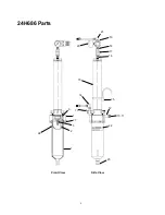
Page 6: ...24H686 Parts 15 20 16 25 24 3 2 1 Front View Side View 21 14 12 23 22 10 11 13 17 18 19 27 7 9 6 ...

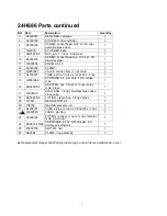
Page 7: ...0 x npt 1 15 G0350088 CYLINDER air 2 in bore 10 in stroke male 1 16 94 0499 96 ADAPTER hex 1 4npt x 1 8 npt male x male brass 1 17 J0000018 COUPLING 1 8 npt stainless steel open close valve 1 18 94 0525 96 FITTING nipple hex 1 8 npt brass 1 19 110341 REGULATOR air 1 20 108190 GAUGE pressure air 1 21 A4000151 TUBE airline tube x 1 8 npt 90 x npt 1 22 L0000095 LABEL warning 1 23 A8000124 FITTING red...

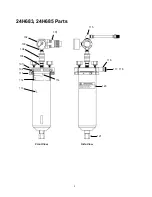
Page 8: ...24H683 24H685 Parts Front View Side View 121 120 117 118 116 115 101 114 113 112 110 108 107 105 104 103 102 8 ...

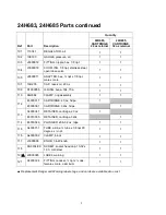
Page 9: ... RING buna 334 70a 1 1 110 24H682 CLAMP ring assembly 1 1 112 E3000017 CARTRIDGE 20 oz hdpe 1 E3000061 CARTRIDGE 32oz hdpe 1 113 A4000047 RETAINER cartridge 20 oz 1 E3010005 RETAINER cartridge 32oz 1 114 E3000046 PLUNGER 20 32 oz ldpe 1 1 115 A4000151 TUBE airline tube x 1 8 npt 90 degree x npt 1 1 116 A4000002 CLAMP block 1 1 117 J3000006 KNOB 1 4 20 knob 1 1 118 96 0334 99 SCREW socket head cap ...

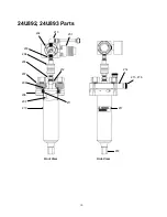
Page 10: ...24U892 24U893 Parts Front View Side View 218 217 215 216 214 201 212 213 206 209 208 207 205 204 203 202 210 211 10 ...

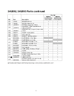
Page 11: ...oir 1 1 208 16X476 GASKET cartridge retainer 1 1 209 E3000044 CARTRIDGE 12 oz hdpe 1 E3000041 CARTRIDGE 6 oz hdpe 1 210 C04069 RETAINER cartridge 12 oz 1 C04091 RETAINER cartridge 6 oz 1 211 E3000007 PLUNGER 2 5 12 oz ldpe 1 1 212 A4000083 CAP adapter 1 1 213 A4000151 TUBE airline 1 4 tube x 1 8 npt 1 1 214 A4000002 CLAMP 1 1 215 J3000006 KNOB 1 4 20 knob 1 1 216 96 0334 99 SCREW socket head cap 1...

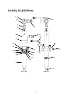
Page 12: ...24U894 24U895 Parts Front View Side View 323 324 325 322 329 312 315 311 303 302 305 307 306 314 309 310 301 304 313 327 321 326 320 328 325 317 318 319 12 ...

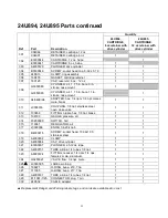
Page 13: ... x male brass 1 1 311 J0000018 COUPLING 1 8 npt stainless steel open close valve 1 1 312 103656 FITTING nipple hex 1 8 npt brass 1 1 313 108190 GAUGE pressure air 1 1 314 F0200099 SWITCH hall 1 1 315 110341 REGULATOR air 1 1 317 J3000006 KNOB 1 4 20 knob 1 1 318 B4000016 SCREW socket head 10 32x1 00 stainless steel 1 1 319 A4000002 CLAMP 1 1 320 A4000084 CAP drive cylinder 1 1 321 E3000007 PLUNGER...

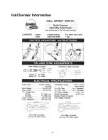
Page 14: ...Hall Sensor Information 14 ...

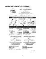
Page 15: ...Hall Sensor Information continued 15 ...

Page 16: ...rson or property or any other incidental or consequential loss shall be available Any action for breach of warranty must be brought within two 2 years of the date of sale GRACO MAKES NO WARRANTY AND DISCLAIMS ALL IMPLIED WARRANTIES OF MERCHANTABILITY AND FITNESS FOR A PARTICULAR PURPOSE IN CONNECTION WITH ACCESSORIES EQUIPMENT MATERIALS OR COMPONENTS SOLD BUT NOT MANUFACTURED BY GRACO These items ...

Reviews: