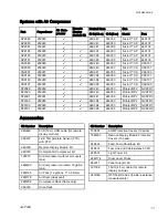
Proportioner Models
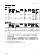
Proportioner Models
E-30i Series
Includes:
Part
Available
Auxiliary
Current at
240 V, 60
Hz*
Booster
Heat
(4000
Watts)
Air
Compressor
(5000 Watts)
Voltage
(phase)
Total
System
Load †
(Watts)
Max Flow
Rate lb/min
(kg/min)
Approxi-
mate Out-
put per Cy-
cle (A+B)
gal. (liter)
Maximum
Fluid
Working
Pressure
psi (MPa,
bar)
259079
50 Amps
240 V (1)
7,700
30 (13.5)
0.0272
(0.1034)
2000 (14,
140)
259080
32 Amps
240 V (1)
11,700
30 (13.5)
0.0272
(0.1034)
2000 (14,
140)
259089
30 Amps
240 V (1)
7,700
30 (13.5)
0.0272
(0.1034)
2000 (14,
140)
259090
12 Amps
240 V (1)
16,700
30 (13.5)
0.0272
(0.1034)
2000 (14,
140)
E-XP2i Series
Includes:
Part
Available
Auxiliary
Current at
240 V, 60
Hz*
Booster
Heat
(4000
Watts)
Air
Compressor
(5000 Watts)
Voltage
(phase)
Total
System
Load †
(Watts)
Max Flow
Rate gpm
(lpm)
Approxi-
mate Output
per Cycle
(A+B) gal.
(liter)
Maximum
Fluid
Working
Pressure psi
(MPa, bar)
259081
32 Amps
240 V (1)
11,700
2.0 (7.6)
0.0203
(0.0771)
3500 (24.1,
241)
259091
12 Amps
240 V (1)
16,700
2.0 (7.6)
0.0203
(0.0771)
3500 (24.1,
241)
Total system watts used by system, based on maximum heated hose length of 310 ft (94.5 m) for
each unit.
*
Full load amps available for auxiliary equipment when all bare-system components are operating
at maximum capabilities. Available auxiliary current is based on 310 ft (94.5 m) of heated hose.
An additional 3.0 amps of auxiliary current is available for each 50 ft (15.2 m) section of heated
hose that is not used.
Available auxiliary current will be less when the engine is de-rated for site altitude. Reduce the
Available Auxiliary Current in the chart by 2.5 Amps per 1000 ft (300 m) elevation increments. If the
available auxiliary current is less than zero, the system configuration may not support the full load
at that altitude.
Includes Complete Air Compressor Kit 24K335.
Refer to Circuit Breaker Configuration Options, page 29.
See Approvals, page 10.
3A1705E
9
Summary of Contents for 259079
Page 34: ...Setup A5 A1 A2 AS AN A3 AT A3 A4 A2 A6 A4 34 3A1705E...
Page 45: ...Advanced Display Module ADM Operation Setup Screens Navigation Diagram Figure 35 3A1705E 45...
Page 49: ...Advanced Display Module ADM Operation Run Screens Navigation Diagram Figure 36 3A1705E 49...
Page 93: ...Dimensions Dimensions Top View Figure 43 Side View Figure 44 3A1705E 93...
Page 95: ...Dimensions Pallet Mounting Dimensions Figure 48 3A1705E 95...
Page 97: ...Notes Notes 3A1705E 97...


