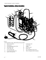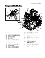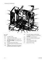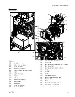
Component Identi
fi
cation
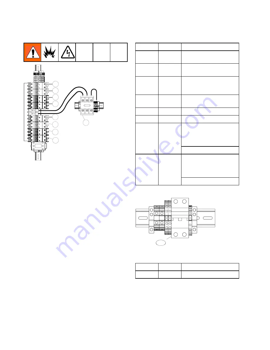
Circuit Breakers
CB01
CB02
CB03
CB04
CB05
CB06
CB07
CB08
CT01
Circuit Breakers Inside Electrical Enclosure (DB)
Figure 18
Note
Not all wires are shown.
Ref.
Size
Component
CB01
30 A
High Power Temperature
Control Module (HPTCM)
CB02
20 A
Motor Control Module
(MCM)
CB03
5 A
Two Motor Fans, Cabinet
Fan, Power Supply, and
Coolant Circulation Pump
CB04*
30 A
Auxiliary Power (Air
Compressor)
CB05*
10 A
Auxiliary Power
CB06*
20 A
Auxiliary Power
E-XP2i and E-30i With
Heat: Low Power
Temperature Control
Module (LPTCM) A
CB07
15 A
E-30i: Auxiliary
E-XP2i and E-30i With
Heat: Low Power
Temperature Control
Module (LPTCM) B
CB08
15 A
E-30i: Auxiliary
* See Circuit Breaker Configuration Options, page 29.
CB20
Circuit Breakers Inside Proportioner Cabinet
Figure 19
Ref.
Size
Component
CB20
50 A
Heated Hose
28
3A1705E
Summary of Contents for 259079
Page 34: ...Setup A5 A1 A2 AS AN A3 AT A3 A4 A2 A6 A4 34 3A1705E...
Page 45: ...Advanced Display Module ADM Operation Setup Screens Navigation Diagram Figure 35 3A1705E 45...
Page 49: ...Advanced Display Module ADM Operation Run Screens Navigation Diagram Figure 36 3A1705E 49...
Page 93: ...Dimensions Dimensions Top View Figure 43 Side View Figure 44 3A1705E 93...
Page 95: ...Dimensions Pallet Mounting Dimensions Figure 48 3A1705E 95...
Page 97: ...Notes Notes 3A1705E 97...

