Setup
Install Wall (optional)
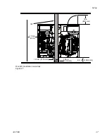
Install a wall between the proportioner and generator
to:
•
Temperature condition the trailer space where
chemical is stored. Check with chemical
manufacturer for chemical storage temperatures.
•
Reduce noise for the operator while the Reactor
is running.
The supplied fuel lines and battery cable may need
to be replaced if a wall is installed between the
proportioner and generator. Purchase the Fuel Line
and Battery Cable Extension Kit 24K333.
1.
If necessary drain coolant from system. See
Drain Coolant, page 69. Coolant lines do not
need to be disconnected to install a wall.
Note
Battery must be connected to starter to
drain coolant from system.
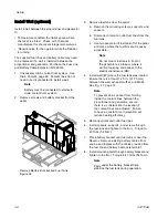
2.
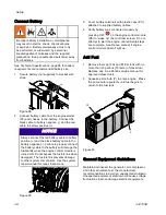
Remove screws and battery bracket from the
pallet.
Remove Battery Bracket and Fuel Tank
Figure 26
3.
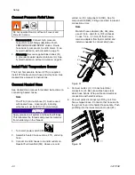
Remove fuel tank from the pallet.
a.
Remove the mounting screws, supports, and
spacers.
b.
Disconnect inlet and outlet fuel lines from the
fuel tank.
c.
Use two people to lift fuel tank off of the pallet
and place where the fuel fill spout is easily
accessible.
Note
Do not mount fuel tank in front of
the generator air intake or where it
will limit opening and access to the
electrical enclosure (DB).
4.
Install wall (IW) where the fuel tank was located.
Ensure there is at least 1.25 in. (31.75 mm)
between the wall, exhaust muffler, and MCM.
Note
To prevent an air pocket from forming
inside the coolant lines between the
proportioner and generator, ensure
there is a constant rise in elevation if
the coolant lines are adjusted. Failure
to have a constant rise in elevation will
reduce heating efficiency.
5.
Reconnect inlet and outlet fuel lines.
6.
Install spacers, supports, and screws through
the fuel tank and tighten to the floor. Torque to
40 ft-lbs (54 N•m).
7.
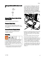
Place battery bracket over fuel tank or near the
Reactor. Remove existing battery cables from
engine and replace with the cables provided from
the fuel line and battery cable extension kit.
8.
Install mounting bolts through battery bracket and
tighten to the floor. Torque to 40 ft-lbs (54 N•m).
Note
Pads under the battery bracket help
stabilize the fuel tank during operation.
36
3A1705E
Summary of Contents for 259079
Page 34: ...Setup A5 A1 A2 AS AN A3 AT A3 A4 A2 A6 A4 34 3A1705E...
Page 45: ...Advanced Display Module ADM Operation Setup Screens Navigation Diagram Figure 35 3A1705E 45...
Page 49: ...Advanced Display Module ADM Operation Run Screens Navigation Diagram Figure 36 3A1705E 49...
Page 93: ...Dimensions Dimensions Top View Figure 43 Side View Figure 44 3A1705E 93...
Page 95: ...Dimensions Pallet Mounting Dimensions Figure 48 3A1705E 95...
Page 97: ...Notes Notes 3A1705E 97...


