Setup
Connect Battery
Improper battery installation or maintenance
may result in electric shock, chemical burns,
or explosion. Battery maintenance must only
be performed or supervised by personnel
knowledgeable of batteries and the required
precautions. Keep unauthorized personnel away
from batteries.
See Technical Specifications, page 98 for battery
requirements and recommended battery size.
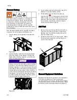
1.
Secure battery (not supplied) to bracket with
strap.
PC
Figure 28
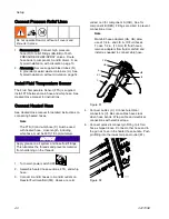
2.
Connect battery cable from the engine starter
(ST) and chassis to the battery. Connect the
black cable to battery negative (-) and the red
cable to battery positive (+).
NOTICE
Always connect the red battery cable to battery
positive (+) and the black battery cable to the
battery negative (-). Failure to properly connect
the battery cable to the battery will damage the
fusible link when the engine control module is
turned ON. Do not bypass the fusible link when
damaged. The fusible link prevents damage
to other system components. See the system
repair manual for repair instructions.
Figure 29
3.
Cover battery terminals with plastic caps (PC)
attached to supplied battery cables.
4.
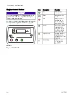
Verify battery was connected properly by
pressing OFF
on the engine control module
(PE) to “wake up” the controller screen. Do not
attempt to start the engine until all Setup steps
are complete. See Repair manual if engine
control module doesn’t light up.
Add Fuel
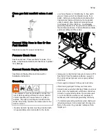
1.
Remove fuel cap (FS) and fill fuel tank with no
more than 20 gallons (75 liters) of diesel fuel.
Replace cap. See Perkins engine manual for
approved diesel fuels.
2.
Squeeze prime bulb (P) to prime engine. Press
the prime bulb repeatedly until fuel begins to
return to the fuel tank.
FS
P
Figure 30
General Equipment Guidelines
Maintain and inspect the generator, air compressor,
and other equipment per the manufacturer
recommendations to avoid an unexpected shutdown.
Unexpected equipment shutdown will cause voltage
fluctuations that can damage electrical equipment.
38
3A1705E
Summary of Contents for 259079
Page 34: ...Setup A5 A1 A2 AS AN A3 AT A3 A4 A2 A6 A4 34 3A1705E...
Page 45: ...Advanced Display Module ADM Operation Setup Screens Navigation Diagram Figure 35 3A1705E 45...
Page 49: ...Advanced Display Module ADM Operation Run Screens Navigation Diagram Figure 36 3A1705E 49...
Page 93: ...Dimensions Dimensions Top View Figure 43 Side View Figure 44 3A1705E 93...
Page 95: ...Dimensions Pallet Mounting Dimensions Figure 48 3A1705E 95...
Page 97: ...Notes Notes 3A1705E 97...

