Setup
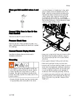
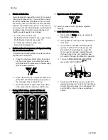
Close gun fluid manifold valves A and
B
Connect Whip Hose to Gun Or Gun
Fluid Manifold
See hose manual for proper connections.
Pressure Check Hose
See hose manual. Pressure check for leaks. If no
leaks, wrap hose and electrical connections to protect
from damage.
Connect Remote Display Module
See Remote Display Module kit manual for
installation instructions.
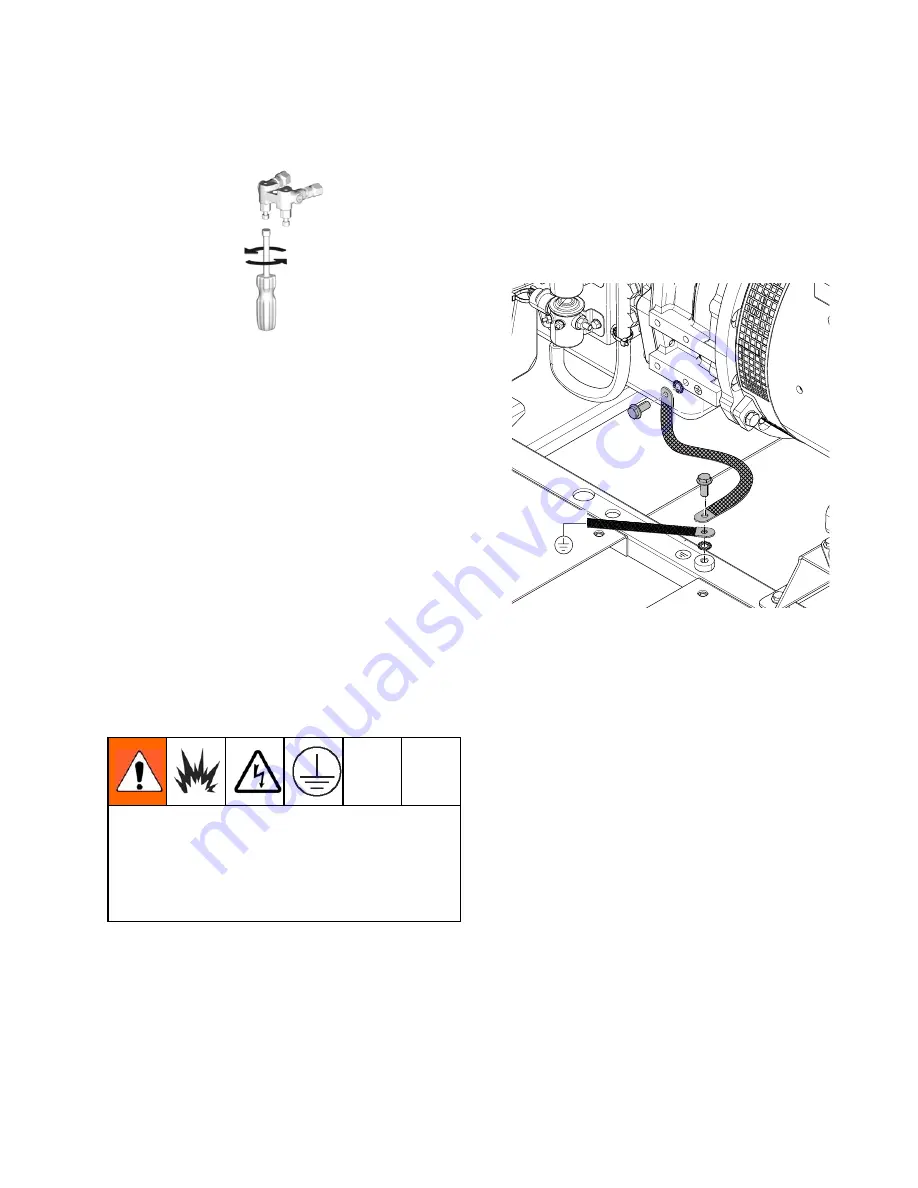
Grounding
The equipment must be grounded to reduce the
risk of static sparking and electric shock. Electric
or static sparking can cause fumes to ignite or
explode. Improper grounding can cause electric
shock. Grounding provides an escape wire for the
electric current.
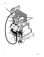
•
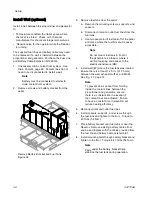
Reactor System:
System must be grounded with
an appropriately sized conductor to the trailer
or vehicle chassis or, if stationary, to true earth
ground. Remove bolt and braided cable from
pallet. Install grounding cable terminated with a
ring terminal (cable and terminal not supplied)
under braided cable. Reinstall bolt and torque
to minimum 25 ft-lbs (34 N∙m). An alternate
grounding location is to the ground bar (CB02) in
the electrical enclosure. Follow all National, State,
and Local safety and fire codes.
•
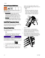
Spray gun:
connect whip hose ground wire to FTS.
See Install Fluid Temperature Sensor, page 40.
Do not disconnect ground wire or spray without
whip hose.
•
Fluid supply containers:
follow your local code.
•
Object being sprayed:
follow your local code.
•
Solvent pails used when flushing:
follow your local
code. Use only metal pails, which are conductive,
placed on a grounded surface. Do not place pail
on a nonconductive surface, such as paper or
cardboard, which interrupts grounding continuity.
•
To maintain grounding continuity when flushing or
relieving pressure,
hold a metal part of spray gun
firmly to the side of a grounded
metal
pail, then
trigger gun.
3A1705E
41
Summary of Contents for 259079
Page 34: ...Setup A5 A1 A2 AS AN A3 AT A3 A4 A2 A6 A4 34 3A1705E...
Page 45: ...Advanced Display Module ADM Operation Setup Screens Navigation Diagram Figure 35 3A1705E 45...
Page 49: ...Advanced Display Module ADM Operation Run Screens Navigation Diagram Figure 36 3A1705E 49...
Page 93: ...Dimensions Dimensions Top View Figure 43 Side View Figure 44 3A1705E 93...
Page 95: ...Dimensions Pallet Mounting Dimensions Figure 48 3A1705E 95...
Page 97: ...Notes Notes 3A1705E 97...

