23
309077
Installation
Graco Factory P, I, and D Settings
Table 4 lists the P, I, and D settings for standard con-
trol panels. These settings are preset at the factory.
Use the table for reference information only.
Table 4. Graco Factory P, I, and D Settings
Category
P
I
D
Unit Voltage
Follower
2
326
49
480
Pump
4.2
1081
162
480
Hose
.8
63
9
480
Gun
2.1
126
19
480
Manifold
1.7
109
16
480
Compensator
1.1
28
4
480
Compare the P, I, and D settings that you recorded for
your site with the Graco factory P, I, and D settings for
standard control panels.
Configuring Temperature Controllers for
Unused Heated Zones
If you are not using all the temperature controllers for
your current application, you
must
turn off the unused
controllers. If any heat zone is not being used and its
temperature controller is not turned off, the supply unit
will experience a high temperature fault when power is
applied to the supply unit.
To turn off the unused controllers, perform the follow-
ing procedure:
NOTE:
Refer to Figure 6, Table 1, and Table 2 for
user information about the E5CK controller.
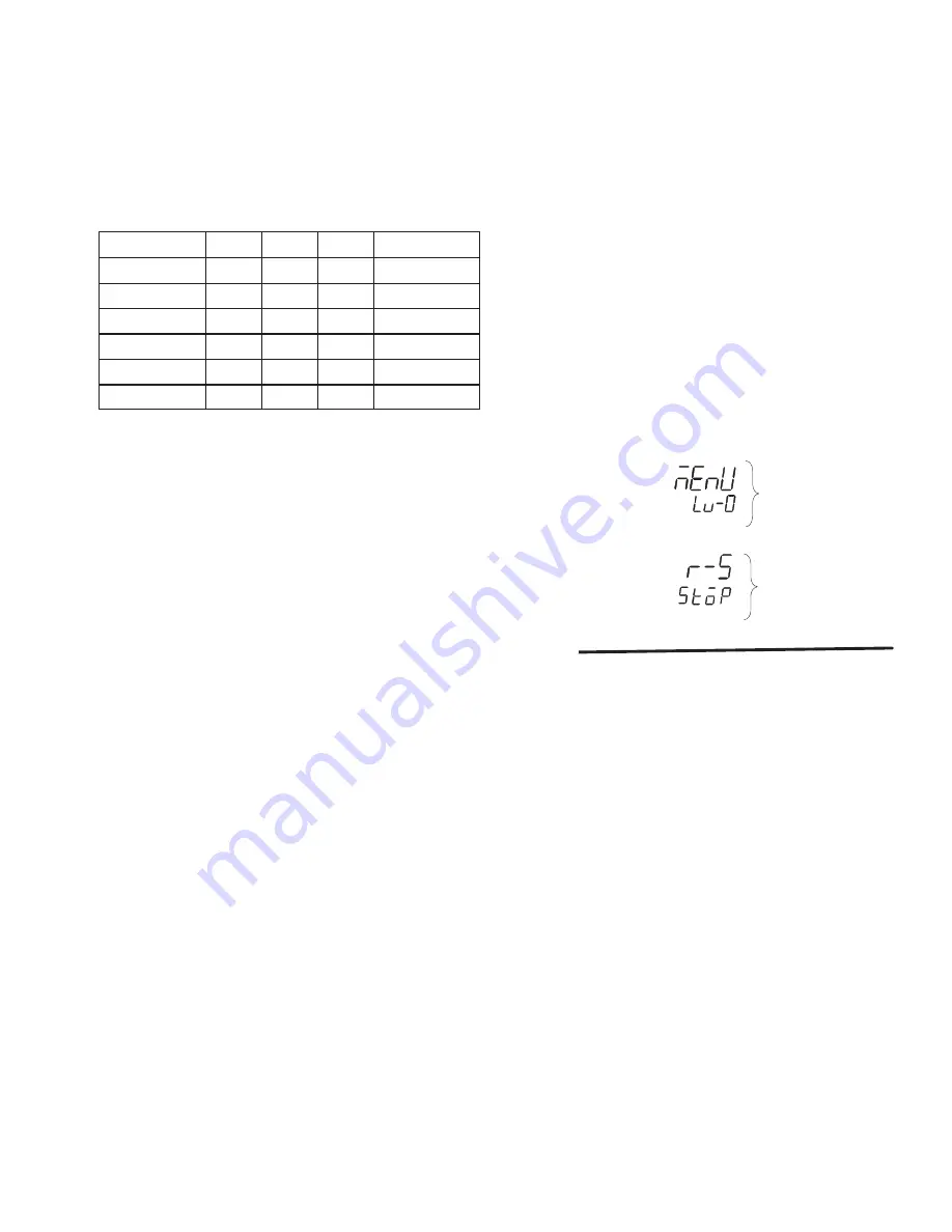
1. Press the mode key (X) twice to display the Run/
Stop option, which is displayed in Level 0 (Fig. 22).
2. Press arrow key (Z) to set the function to the Stop
mode (See Fig. 22). Verify that the stop light turns
on.
Fig. 22
RUN/STOP
FUNCTION
FUNCTION
MODE
LEVEL
MODE
3. To avoid actuating the alarm, disable the alarm 2
setting while in the stop mode. See
Disabling the
Alarm 2 Setting
on page 18.
Summary of Contents for 309077
Page 9: ...9 309077 Typical Installation 4 Regulator Air Control Module Fig 2 O C D I A E B 9402A ...
Page 47: ...47 309077 Notes ...
Page 64: ...64 309077 Schematics 122 122 ...
Page 65: ...65 309077 Schematics 121 121 TEMPERATURE CONTROL TEMPERATURE CONTROL ...
Page 66: ...66 309077 Schematics 170 170 TEMPERATURE CONTROL TEMPERATURE CONTROL TEMPERATURE CONTROL ...
Page 68: ...68 309077 Schematics ...
Page 69: ...69 309077 Notes ...


