background image

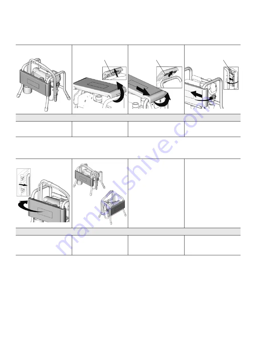
Platform Transport Position (826098) 

16

310820H

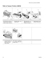
Platform Transport Position (826098)

Attach the platform to the side of 
the sprayer frame to access the 
handle and transport the sprayer.

1

Lift platform off peg (P) side 
of sprayer frame.

2

Slide guiding plate (G) off 
opposite side of frame and 
lift platform off of sprayer. 

3

Slide guiding plate (G) onto 
either side of sprayer frame. 

4

Align clips on opposite side 
of platform with sprayer 
frame and push until it 
snaps onto frame.

NOTE: Platform is reversible and 
can be attached to either side of 
the sprayer frame.

ti11584a

P

ti11605a

G

ti11607a

G

ti11603a

ti11604a

ti11584a

ti11606a

Summary of Contents for 310820H

Page 1: ...portable spray applications of architectural paints and coatings 3300 psi 227 bar 22 7 MPa Maximum Working Pressure Important Safety Instructions Read all warnings and instructions in this manual Sav...

Page 2: ...arning 3 Component Identification 6 Pressure Relief Procedure 7 Grounding 8 9 Setup 9 Startup 11 Clearing Clogs 13 Platform Access Position 826098 15 Platform Transport Position 826098 16 16 Technical...

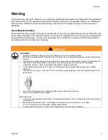
Page 3: ...e cord or plug is required do not connect the grounding wire to either flat blade terminal The wire with insulation having an outer surface that is green with or without yellow stripes is the groundin...

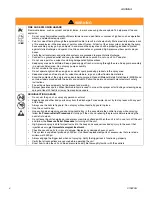
Page 4: ...d container labels provided with the paints and solvents Follow the paint and solvents manufacturer s safety instructions Fire extinguisher equipment shall be present and working Sprayer generates spa...

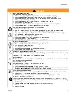
Page 5: ...ctrical outlets Use only 3 wire extension cords Ensure ground prongs are intact on sprayer and extension cords Do not expose to rain Store indoors PRESSURIZED ALUMINUM PARTS HAZARD Do not use 1 1 1 tr...

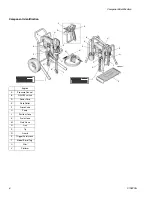
Page 6: ...A Pressure Control B ON OFF switch D Power Cord E Fluid Outlet F Prime Valve H Pump J Suction Hose K Drain Hose M Fluid Hose N Gun P Tip R Guard S Trigger Safety Lock T Model Serial Tag U Filter V Pla...

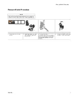
Page 7: ...ontrol to lowest pressure 2 Hold gun against side of grounded metal flushing pail Trigger gun to relieve pressure 3 Turn prime valve down If you suspect spray tip or hose is clogged or pressure is not...

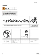
Page 8: ...ged into an outlet that is properly installed and grounded in accordance with all local codes and ordinances Power Requirements Extension Cords Do not modify plug If it will not fit in outlet have gro...

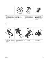
Page 9: ...metal pail connect a ground wire to the pail by clamping one end to pail and other end to a true earth ground such as a water pipe To maintain grounding continuity when flushing or relieving pressure...

Page 10: ...d into a properly grounded electrical outlet 9 Turn prime valve down 10 Place siphon tube set in grounded metal pail pratially filled with flushing fluid See Grounding page 9 Do steps 1 6 of Startup p...

Page 11: ...lve horizontal Take spray gun trigger safety OFF 5 Hold gun against grounded metal flushing pail Trigger gun and flush 1 minute 6 Inspect for leaks Do not stop leaks with hand or a rag If leaks occur...

Page 12: ...9 1 Spray test pattern Adjust pressure to eliminate heavy edges 2 Use smaller tip size if pressure adjustment cannot eliminate heavy edges 3 Hold gun perpendicular 10 12 in from surface Spray back and...

Page 13: ...ke safety OFF and continue spraying 1 Relieve Pressure page 7 2 Remove guard and Spray Tip For additional information see gun manual 309639 3 Remove siphon tube set from paint Wipe excess paint off ou...

Page 14: ...bove flushing fluid 10 Close drain valve Trigger gun into flushing pail to purge fluid from hose 11 Turn pressure control knob all the way down and power switch OFF Unplug sprayer 12 If you have a fil...

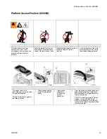
Page 15: ...table intermediate stepping device The sprayer platform is reversible and can be installed facing either direction To install the platform perform the following steps 1 Slide platform guiding plate G...

Page 16: ...e of sprayer frame 2 Slide guiding plate G off opposite side of frame and lift platform off of sprayer 3 Slide guiding plate G onto either side of sprayer frame 4 Align clips on opposite side of platf...

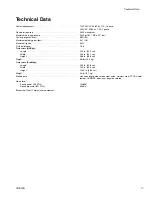
Page 17: ...delivery gpm lpm 0 47 1 8 Maximum tip size 0 021 Fluid outlet npsm 1 4 in Dimensions Hi Boy Length 22 0 in 55 9 cm Width 20 5 in 52 1 cm Height 38 8 in 98 6 cm Weight 58 lbs 25 9 kg Dimensions ProSte...

Page 18: ...aimed defect If the claimed defect is verified Graco will repair or replace free of charge any defective parts The equipment will be returned to the original purchaser transportation prepaid If inspec...

Reviews: