

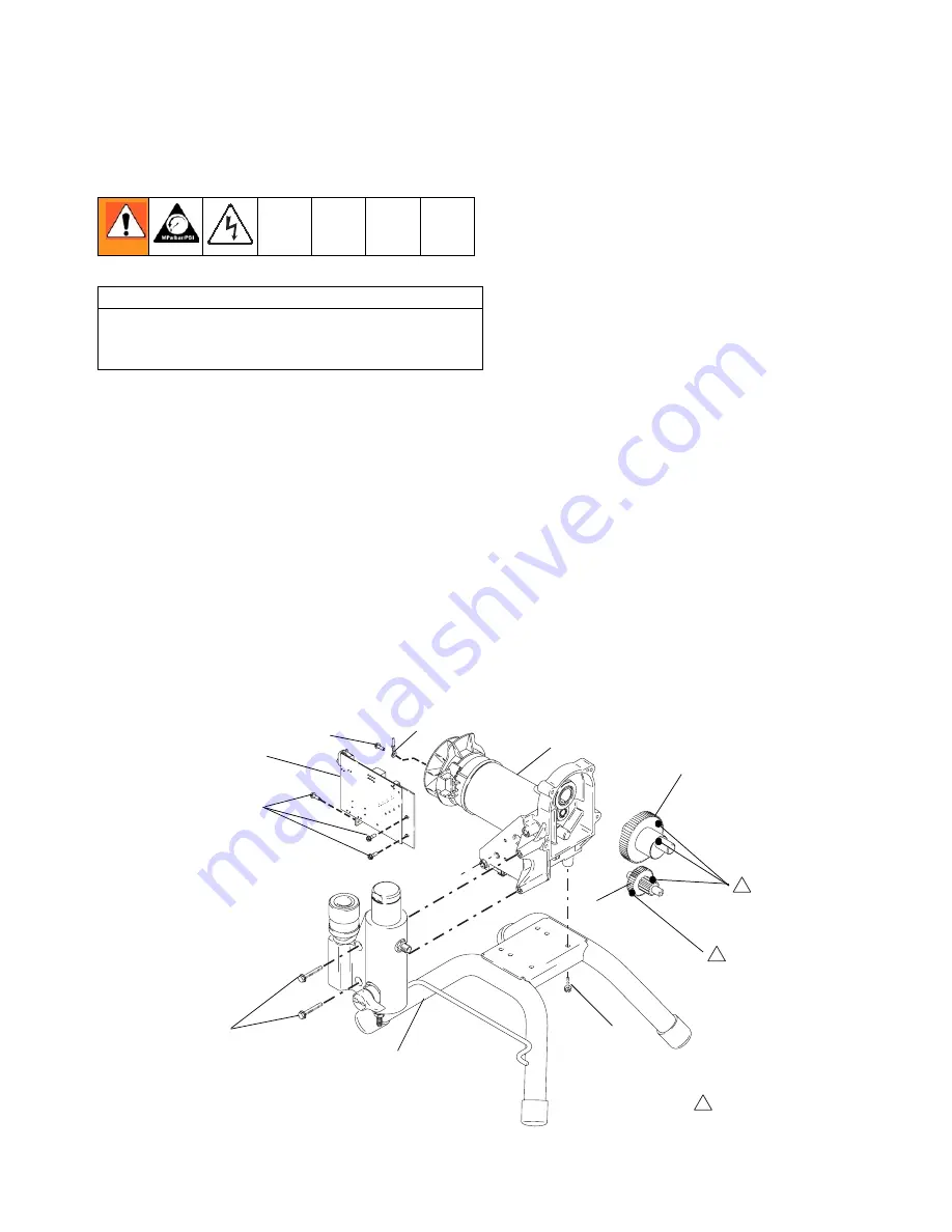
Motor Replacement
311737B
27
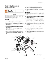
Motor Replacement
See Wiring Diagram, page 28.
Removal
1.
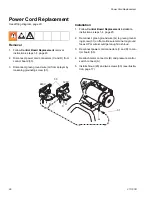
Relieve pressure
, page 8. Disconnect power cord
from outlet.
2.
Remove pump (9).
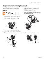
Displacement Pump Replace-
ment
, page 14.
3.
Remove drive housing,
Drive Housing Replace-
ment
, page 16.
4.
Remove Pressure (Fluid) Manifold,
Manifold
Replacement
, page 24.
5.
Disconnect all leads from board (33) and remove
control board.
Control Board Replacement
, page
20.
6.
Remove ground wire (G) from motor endbell.
7.
Remove four screws (6) and motor (1) from frame
(45).
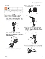
Installation
1.
Install new motor (1) on frame (45) with four screws
(6).
2.
Install manifold (15) with two screws (6).
Manifold
Replacement
, page 24
3.
Install control board (33) with three screws (30).
Connect all leads to board. See
Control Board
Replacement
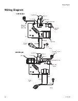
, page 20 and
Wiring Diagram
, page
28.
4.
Connect ground wire (G) to motor with green ground
screw (31).
5.
Install Drive Housing.
Drive Housing Replace-
ment
, page 16.
6.
Install pump (9).
Displacement Pump Replace-
ment
, page 14.
7.
Install shroud (29) with two screws (30) (see illustra-
tion, page 17).
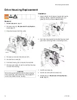
CAUTION
Do not drop gear cluster (3) and (2) when removing
drive housing (5). Gear cluster may stay engaged in
motor frontend bell or drive housing.
31
33
30
6
1
3
2
6
45
34
1
1
Liberally apply grease
1
ti5642b
Summary of Contents for 390 253958
Page 30: ...Notes 30 311737B Notes...


