background image

8

307–452

Operation

Pressure Relief Procedure

PRESSURIZED EQUIPMENT HAZARD
The system pressure must be manually relieved to
prevent the system from starting or spraying acci-
dentally. To reduce the risk of an injury from acci-
dental spray from the gun, splashing fluid, or mov-
ing parts, follow the Pressure Relief Procedure
whenever you:

D

are instructed to relieve the pressure,

D

stop spraying,

D

check or service any of the system equipment,

D

or install or clean the spray nozzles.

WARNING

1.

Turn off the air and fluid supply to the gun.

2.

Trigger the gun into a grounded metal waste con-
tainer to relieve system pressures.
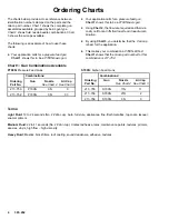
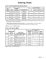
Filter the Fluid

Strain or filter the fluid to remove coarse particles and
sediment, then check the viscosity of the fluid. Install
the proper needle/nozzle set and air cap combination
selected from the charts on page 5.

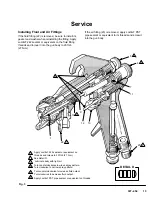
Adjusting the Spray Pattern (See Fig. 3)

The desired pattern, volume of fluid output and degree
of atomization can easily be obtained by regulating the
fan adjustment valve (5) and the fluid adjustment
knob (6).

Adjust the Pattern Size

Turn the fan adjustment valve (5) out (counterclock-
wise) to make the spray pattern wider.

Adjust the Fluid Output Volume for Pressure Feed

Turn the fluid adjustment knob (6) out all the way
(counterclockwise). Then adjust the air pressure at the
pressure feed tank until the desired fluid flow is ob-
tained. For the final adjustment, turn the fluid adjust-
ment knob in (clockwise) to reduce the volume of fluid
output until the desired results are obtained.

Adjust the Fluid Output Volume for Siphon or 
Gravity Feed

Turn the fluid adjustment  knob (6) in (clockwise) to
reduce the volume of fluid output, and turn it out (coun-
terclockwise) to increase the fluid output.

NOTE: If the fluid adjustment knob is turned in all the
way, the gun will emit only air.

Test the Spray Pattern

Hold the gun about 10 in. (254 mm) away from the sur-
face of the test piece. Adjust the air pressure to the
gun until proper atomization is achieved. Use the low-
est possible air pressure to obtain the desired results.

NOTE: The air adjustment valve (17) can also be used
to regulate air at the gun.

Continuous Spraying

Leave the fan and fluid adjustment valves in the full
open positions.  This provides maximum fluid flow and
prevents premature wear on the fluid nozzle. Use sep-
arate regulators to control the air and fluid flow to the
gun.

Short-term Operations

The pattern size and fluid output volume may be re-
duced by turning in the fan and fluid adjustment valves.

Spray Pattern Direction

WARNING

To reduce the risk of serious injury whenever you
are instructed to relieve pressure, always follow the
Pressure Relief Procedure at left.

The

 direction of the spray pattern is determined by the

position of the air cap (3). The horns of the air cap
should be the opposite direction (horizontal or vertical)
of the desired direction of the spray pattern. To change
the spray pattern direction, first relieve the pressure.
Then loosen and turn the air cap to the desired position
and hand tighten the air cap securely.

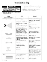
Proper pattern adjustment will give a spray pattern
shaped like this:

Vertical Pattern

Horizontal Pattern

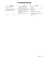
See the Troubleshooting Chart for the cause and so-
lution of improper spray patterns.

Summary of Contents for 700N

Page 1: ...ing numbers and descriptions Table of Contents Warnings 2 Ordering Charts 4 Installation 6 Operation 8 Maintenance 9 Troubleshooting 10 Service 12 Parts 14 Air Flow Charts 16 Dimensional Drawing 18 Te...

Page 2: ...s equipment has a 100 psi 7 bar maximum working fluid pressure and a 100 psi 7 bar maximum working air pressure D Use fluids and solvents which are compatible with the equipment wetted parts Refer to...

Page 3: ...or rag D Follow the Pressure Relief Procedure on page 8 whenever you are instructed to relieve the pressure stop spraying clean check or service the equipment or install or clean the fluid nozzle D Ti...

Page 4: ...g Chart 3 you determine that the 0 air cap is best for the application D This makes your combination a P700N 03N 0 Chart 1 shows that the Graco part number for this combination is 217 752 Chart 1 Gun...

Page 5: ...o 108 704 can be used with 0 047 in 1 2 mm and 0 055 in 1 4 mm orifice size Typical use is for extremely light viscosity fluids such as stains and dyes NOTE See page 17 for Fluid Flow Charts Chart 3 A...

Page 6: ...follow all local safety and fire codes Installation Procedure NOTE See Accessories section for information on recommended accessories 1 Install an air filter G in the gun air supply line to ensure a c...

Page 7: ...7 307 452 Installation NOTE On the gravity gun gravity cups connect to the gun at a fluid inlet on the side of the gun See Fig 2 Fig 2 04837 A B KEY A Gravity Cup B Gravity Gun Fluid Inlet 3 8 npsm...

Page 8: ...ned Adjust the Fluid Output Volume for Siphon or Gravity Feed Turn the fluid adjustment knob 6 in clockwise to reduce the volume of fluid output and turn it out coun terclockwise to increase the fluid...

Page 9: ...m the gun passages 2 Relieve the pressure 3 Wipe the outside of the gun clean with a solvent dampened cloth 4 If the air cap and fluid nozzle need cleaning re lieve the pressure and remove the air cap...

Page 10: ...tighten packing nut 9 Fluid build up on air cap partially clogged horn holes Full air pressure from clean horn hole forces fan pattern toward clogged end Damaged fluid nozzle or air cap holes Clean w...

Page 11: ...e packings 10 Replace Air leakage from front of gun Air valve 12 13 not seating properly Clean service Fluid leakage from front of gun Needle 1 worn or damaged Replace Worn needle and nozzle seat in f...

Page 12: ...ing nut 9 tighten the nut If leakage does not stop re move the fluid adjusting valve knob 6 spring 7 and needle 1 See Fig 3 2 Unscrew the packing nut 9 and remove the old packings 10 A small hooked to...

Page 13: ...apply Loctiter PST pipe sealant or equivalent to its threads and screw it into the gun body Fig 3 6 7 11 13 12 9 1 10 22 DETAIL D 4 5 5 23 6 2 1 3 1 Apply Loctiter 242 sealant or equivalent on threads...

Page 14: ...14 307 452 Parts Model 700N Includes items 1 23 20 21 17n 11 12 13n 3 2 4 15 18 8 7 6 1 5 16 9 10 22 23 19 14 04868 19...

Page 15: ...packing needle 1 10 106 885 KIT packing needle 1 11 105 608 SPRING compression air valve 1 12 106 731 VALVE air needle 1 13n 106 732 KIT packing air valve 1 14 106 730 TRIGGER 1 15 105 606 SCREW pivot...

Page 16: ...zontal axis note the air pressure that will be used 3 Go up vertically until you intersect the actual flow line 4 Go across and read the flow in cfm Model 700N 0N 0 700N 0N 03 Part No 217 750 217 752...

Page 17: ...70 80 Gun Model Nozzle Air Cap Pressure Feed Fluid Flow Charts Model 700N 0N Nozzle Part No 106 750 Gun Model Nozzle 0 200 400 600 800 1000 1200 1400 1600 0 5 10 15 20 25 30 35 40 45 50 FluidFlow cc...

Page 18: ...elastomer Maxiumum working temperature 104_F 40_C Noise data Sound pressure 87 0 Db A Sound power 99 7 Db A All readings were taken with the gun controls fully open with an air inlet pressure of 65 ps...

Page 19: ...0 97 liter non evaporation lubricant for air and fluid packings Siphon Cup PC 12 105 700 34 oz 1000 cc capacity 3 8 npsm f Replacement diaphragm available Order part number 106 776 Replacement lid ga...

Page 20: ...p repairs will be made at a reasonable charge which charges may include the costs of parts labor and transportation DISCLAIMERS AND LIMITATIONS The terms of this warranty constitute purchaser s sole a...

Reviews: