background image

Repair 

14

312579H

Repair

See Parts, page 16, for callout references.

Disassembly

1. Unscrew retaining ring (14) to remove air 

cap (13b). Check o-rings (13a and 13c) 
and replace if necessary.

2. Trigger gun while unscrewing nozzle (11) to 

prevent needle damage.

3. Check o-ring (19) and replace if necessary.

4. Remove fluid control valve (8), spring (26), 

needle (9), and nut (7). Inspect. Replace 
tip (9c), needle (9), and u-cup seal (20) as 
necessary. If replacing needle tip, use low 
strength thread adhesive on needle tip 
threads.

5. Remove spring (28) and push the air valve 

assembly (6) out the back of the gun. 
Inspect. Replace air valve assembly (6) 
and u-cup seal (20) as necessary. Use tool 
(33) to install u-cup seal.

6. Remove trigger nut (22), trigger pin (21), 

wave washer (18), and trigger (10).

7. Unscrew needle packing nut (17) and 

remove u-cup packing (16) and 
spreader (15).

8. Remove air control valve assembly (5). 

Inspect and replace as necessary.

9. Remove air inlet valve assembly (27). 

Inspect and replace as necessary.

Fluid Inlet Fitting Replacement

1. Remove fluid inlet fitting (4).

2. Remove fluid inlet gasket (3) from gun body 

and discard.

3. Apply thread sealant to replacement fluid 

inlet fitting (4) threads.

4. Snap the fluid inlet gasket (3) securely onto 

the fluid inlet fitting (4).

5. Screw in fluid inlet fitting (4) and torque to 

155-165 in.-lb (17.5-18.6 N•m).

6. Replace washer (28) as required.

Follow Pressure Relief Procedure, page 8.

PRESSURIZED EQUIPMENT HAZARD

Fluid inlet gasket (3) must be replaced if 
fluid inlet fitting (4) is removed from spray 
gun.

Failure to replace gasket (3) may result in 
air leakage into the fluid section causing a 
non-vented gravity cup to become
pressurized.

Summary of Contents for AirPro 289002

Page 1: ...and compliant guns for specialty industrial applications For professional use only 100 psi 0 7 MPa 7 bar Maximum Air Inlet Pressure See page 3 for model information Important Safety Instructions Read all warnings and instructions in this manual Save these instructions ti11095A ll 2 G ...

Page 2: ... Organic Compounds VOC Regulation 8 Daily Gun Maintenance 9 General Tasks 9 Flush 9 Clean Gun and Cup 9 Clean Nozzle and Air Cap 10 Compliant Cleaning Methods 10 Troubleshooting 12 Repair 14 Disassembly 14 Fluid Inlet Fitting Replacement 14 Reassembly 15 Parts 16 Accessories 18 Repair Kits 19 Technical Data 20 Graco Standard Warranty 22 Graco Information 22 Related Manuals Manual Language 313089 C...

Page 3: ... Conventional HVLP Compliant Model Series Max HVLP Compliant Air Pressure psi MPa bar Model Series Max HVLP Compliant Air Pressure psi MPa bar Model Series Max HVLP Compliant Air Pressure psi MPa bar 0 055 1 4 289011 A N A 289014 A 29 0 2 2 0 289017 A 35 0 24 2 4 0 070 1 8 289012 A N A 289015 A 29 0 2 2 0 289018 A 35 0 24 2 4 Orifice Size in mm Conventional HVLP Compliant Model Series Max HVLP Com...

Page 4: ... working fire extinguisher in the work area PRESSURIZED EQUIPMENT HAZARD Fluid from the gun dispense valve leaks or ruptured components can splash in the eyes or on skin and cause serious injury Follow Pressure Relief Procedure in this manual when you stop spraying and before cleaning checking or servicing equipment Tighten all fluid connections before operating the equipment Check hoses tubes and...

Page 5: ...d to have a transfer efficiency greater than or equal to HVLP guns The Graco compliant guns have no restrictions on air cap pressures but the gun inlet pres sure must remain under 35 psi 0 24 MPa 2 4 bar to remain in compliance PERSONAL PROTECTIVE EQUIPMENT You must wear appropriate protective equipment when operating servicing or when in the operating area of the equipment to help protect you fro...

Page 6: ...e equipment was tested with lightweight oil which is left in the fluid passages to protect parts To avoid contaminating your fluid with oil flush the equipment with a compatible sol vent before using the equipment See Flush page 9 Check that your shop air provides adequate air flow See Technical Data page 20 for minimum cfm requirements Recommended 5 16 in 7 9 mm ID hose optional 3 8 in 10 mm ID a...

Page 7: ...f turn 6 To reduce fluid flow turn the fluid control valve clockwise 7 Spray a test pattern Evaluate the spray pattern size and atomization 8 To achieve a narrow spray pattern turn air control valve clockwise 9 To improve atomization reduce the fluid flow rate Increasing the air pressure can improve atomization but may result in poor Transfer Efficiency TE or non compliant operation FIG 2 FIG 3 ti...

Page 8: ... the reduced spray velocity pro duced by lower HVLP air pressures along with a larger fluid particle size because there is less air to blow off solvents than is produced by conventional airspray Take care to avoid runs or sags as you spray Volatile Organic Compounds VOC Regulation In certain states spraying solvents that release VOCs into the atmosphere when cleaning a spray gun is prohibited To c...

Page 9: ... the equipment is clean 5 Follow Pressure Relief Procedure page 8 Clean Gun and Cup 1 Flush page 9 2 Dampen a soft cloth with solvent and wring out the excess Point the gun down and wipe off the outside of the gun and cup 3 Make sure cup lid vent hole is clear 4 Blow dry gun inside and out Lubricate CAUTION Solvent left in gun air passages could result in a poor quality paint finish Do not use any...

Page 10: ...ood seal 5 Install the retaining ring 14 and air cap 13 6 After cleaning the gun lubricate the follow ing parts with lubricant 111265 daily fluid control valve threads trigger pivot pin fluid needle shaft Compliant Cleaning Methods 1 Place spray gun in a gun washer that com pletely encloses the gun and components during cleaning rinsing and draining 2 Spray solvent through the spray gun into a clo...

Page 11: ...Daily Gun Maintenance 312579H 11 ...

Page 12: ...for viscosity of material being sprayed Reduce air pressure and increase mate rial viscosity Correct pattern by narrowing fan size with fluid control valve 8 Spray Pattern Dirty or distorted air horn holes Clean and inspect air cap If pattern is not corrected replace air cap Gun spitting Air getting into paint stream Check if cup is empty and fill Tighten fluid nozzle 11 Check and tighten needle p...

Page 13: ...Tighten fluid nozzle 11 Damaged fluid nozzle seal 19 Replace seal 19 Excessive air leak behind trigger Worn u cups air valve Repair gun Kit 289408 Be sure to use all included parts Worn trigger Replace trigger part 289140 If leak per sists repair gun Kit 289408 Problem Cause Solution ...

Page 14: ... 21 wave washer 18 and trigger 10 7 Unscrew needle packing nut 17 and remove u cup packing 16 and spreader 15 8 Remove air control valve assembly 5 Inspect and replace as necessary 9 Remove air inlet valve assembly 27 Inspect and replace as necessary Fluid Inlet Fitting Replacement 1 Remove fluid inlet fitting 4 2 Remove fluid inlet gasket 3 from gun body and discard 3 Apply thread sealant to repl...

Page 15: ... cup packing 16 with open end facing front of gun Install packing nut 17 Torque to 3 in lb 0 3 N m 4 Install wave washer 18 with cupped side toward the gun body Lubricate and apply thread retainer to trigger pin 10 Install trig ger 10 trigger pin 21 and trigger nut 22 Torque to 15 20 in lb 1 7 2 2 N m 5 Install air valve assembly 6 spring 28 and nut 7 Torque to 175 185 in lb 19 8 20 9 N m 6 Instal...

Page 16: ... in lb 9 6 10 2 N m Torque to 15 20 in lb 1 7 2 2 N m Torque to 175 185 in lb 19 8 20 9 N m Torque to 155 165 in lb 17 5 18 6 N m Install with valve assembly turned fully counterclockwise to outermost position Torque to 205 215 in lb 23 2 24 3 N m Torque to 3 in lb 0 3 N m 1 2 3 4 5 6 7 8 9 10 11 12 20 6 5 28 20 7 8 6 8 13c 11 19 21 18 1 9 13b 14 13a 15 2 3 36 27 23 26 9a 9b 9c 22 17 16 3 2 7 4 1 ...

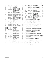
Page 17: ...ALVE air control assembly 1 6 289039 VALVE air assembly 1 7 289052 NUT air valve u cup assembly 1 8 289097 VALVE fluid control 1 9 See p 19 NEEDLE assembly 1 9a NUT needle 1 9b NEEDLE 1 9c See p 19 TIP needle 1 10 289140 TRIGGER 1 11 See p 19 NOZZLE fluid 1 13 See p 19 AIR CAP assembly includes 13a 13c 1 13a WASHER 1 13b O RING 1 13c See p 19 AIR CAP 1 14 RING retaining 1 15 SPREADER u cup 1 16 PA...

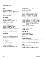
Page 18: ...9655 Swivel Air Valve Part No Description 105749 Cleaning Brush 111265 Gun Lubricant 15C161 Ultimate Gun Cleaning Kit Part No Description 234941 Cup and Collar 6 oz 8 pack 234771 Cup and Collar 25 oz 8 pack 234937 Cup and Collar 32oz 4 pack 234940 Lid and Liner 6 oz 50 pack 234772 Lid and Liner 25 oz 50 pack 234938 Lid and Liner 32 oz 25 pack 234942 Ratio Film insert 6 oz 50 pack 15F531 Ratio Film...

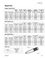
Page 19: ... 9c 5 pack 289011 Conventional 0 055 1 4 289773 289780 289799 289493 288185 289012 Conventional 0 070 1 8 289773 289767 289786 289494 289001 289014 HVLP 0 055 1 4 289771 289776 289786 289495 289001 289015 HVLP 0 070 1 8 289771 289801 289786 289496 289001 289017 Compliant 0 055 1 4 289772 289779 289799 289497 288185 289018 Compliant 0 070 1 8 289772 289559 289799 289498 288185 Model Spray Type Nozz...

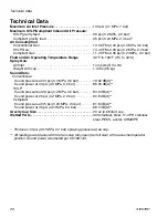
Page 20: ... bar HVLP Gun 14 4 CFM at 29 psi 0 2 MPa 2 0 bar Compliant Gun 11 2 CFM at 35 psi 0 24 MPa 2 4 bar Fluid and Air Operating Temperature Range 32 F to 109 F 0 C to 43 C Spray Gun Air Inlet 1 4 npsm R1 4 19 Weight with cup 1 3 lbs 0 6 kg Sound Data Conventional Sound pressure at 43 psi 0 3 MPa 3 0 bar 79 52 dB A Sound power at 43 psi 0 3 MPa 3 0 bar 88 05 dB A HVLP Sound pressure at 29 psi 0 2 MPa 2 ...

Page 21: ...Technical Data 312579H 21 ...

Page 22: ...al or workmanship repairs will be made at a reasonable charge which charges may include the costs of parts labor and transportation THIS WARRANTY IS EXCLUSIVE AND IS IN LIEU OF ANY OTHER WARRANTIES EXPRESS OR IMPLIED INCLUDING BUT NOT LIMITED TO WARRANTY OF MERCHANTABILITY OR WARRANTY OF FITNESS FOR A PARTICULAR PURPOSE Graco s sole obligation and buyer s sole remedy for any breach of warranty sha...

Reviews: