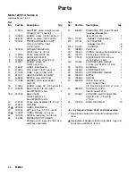
background image

10

308455

Operation

IV.

Set the fluid and air pressure.
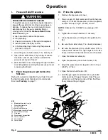
1.

With the system primed and the gun air regulator
closed (36), trigger the gun and adjust the pressure
pot air regulator (33). Refer to Fig. 5. If available, use
the pressure setting provided by your fluid supplier.
Otherwise, use the following instructions to deter-
mine the fluid pressure.

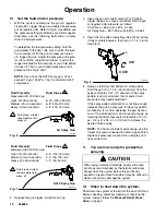
To determine the fluid pressure setting, hold the
gun parallel to the floor. (Be sure to catch the fluid
in a container.) With the gun air pressure turned
off, trigger the gun. Adjust the pressure pot regula-
tor (33) until the straight fluid stream is within the
range indicated for the viscosity of your fluid before
it drops off. That is your optimal pressure pot air
pressure. See Fig. 6 and 7.

NOTE: If you have the HVLP spray gun, do not
exceed 15 psi (103 kPa, 1 bar) to maintain HVLP
compliance.

Fluid Viscosity

Fluid Droop

Measured with #2 Zahn cup

Light (18–25 seconds)

8–10” (200–250 mm)

Medium (25–40 seconds)

6–8” (150–200 mm)

Heavy (40–60 seconds)

4–6” (100–150 mm)

Fig. 6

1

1

Fluid droop: straight
stream before fluid
drops off

1

Air Spray Gun

ti12121A

Fluid Viscosity

Fluid Droop

Measured with #2 Zahn cup

Light (18–25 seconds)

4–6” (100–150 mm)

Medium (25–40 seconds)

2–4” (50–100 mm)

Heavy (40–60 seconds)

1–2” (25–50 mm)

Fig. 7

1

1

Fluid droop; straight 
stream before fluid
drops  off

1

HVLP Spray Gun

ti12121A

2.

Release the gun trigger. Install the air cap.

3.

Open the gun air shutoff valve (17a). Partially
trigger the gun so only air is emitted. Set the gun
air regulator (36) pressure as follows:
HVLP Gun – 60 psi (414 kPa, 4.1 bar)
Air Spray Gun – 65 to 90 psi (448 kPa, 4.5 bar).

4.

Open the fan pattern adjusting valve (E) by turning
it fully counterclockwise, then turn it in 1 to 2 turns.
See Fig. 8.

Fig. 8

E

TI2120A

CW

CCW

5.

Spray a stationary test pattern on scrap paper.
Hold the gun 10 to 12 in. (250–300 mm) from the
paper and spray for 2 or 3 seconds. If the spray
pattern is poorly atomized, the air and/or fluid
pressures may need adjustment.

If the spray pattern atomization is not fine enough,
increase the gun air pressure. If the spray pattern
atomization is too fine, decrease the gun air pres-
sure. If the atomization is still not good enough, try
lowering the fluid pressure in increments of 2 or 3
psi  (14 or 21 kPa, 0.1 or 0.2 bar) to achieve the
desired finish quality.

NOTE: For the most efficient paint usage, use the
lowest air pressure needed to obtain a good finish.
Higher air pressures create more overspray and
uses more fluid.

V.

You are now ready for production
spraying.

CAUTION

When using catalyzed materials, observe the fluid
pot life as recommended by the fluid manufacturer.
Always flush the system before the pot life has
expired to prevent dried fluid which may be difficult to
clean out and may damage the system.

VI.

When to shut down the system.

Shut down the system at the end of the work shift and
before checking, adjusting, cleaning or repairing the
system. Always follow the Pressure Relief Proce-
dure
, on page 9.

Summary of Contents for AirPro 308455K

Page 1: ...m air and fluid hoses and air and fluid controls Model 237413 Series A Complete package includes pressure pot AirPro HVLP spray gun with 0 055 1 4 mm fluid nozzle 25 ft 7 6 m air and fluid hoses and air and fluid controls Instructions Parts List 308455K ENG Important Safety Instructions Read all warnings and instructions in this manual Save these instructions This manual provides basic safety inst...

Page 2: ...ngs daily Replace worn damaged or loose parts immediately Permanently coupled hoses cannot be repaired replace the entire hose D Handle and route hoses and tubes carefully Keep the hoses and tubes away from moving parts and hot surfaces Do not use the hoses to pull equipment Do not expose Graco hoses to tempera tures above 180_F 82_C or below 40_F 40_C FIRE AND EXPLOSION HAZARD Improper grounding ...

Page 3: ...s sharp edges moving parts and hot surfaces Do not expose Graco hoses to temperatures above 180_F 82_C or below 40_F 40_C D Do not use the hoses to pull the equipment D Use fluids or solvents which are compatible with equipment wetted parts See the Technical Data section of all equipment manuals Read the fluid and solvent manufacturer s warnings D Fluid hoses must have spring guards on both ends t...

Page 4: ...pressor for efficient operation 2 Clear obstacles and debris that could cause an unsafe operating environment 3 Bring an air line from your compressed air supply to the pressure pot location Be sure the air is dry and filtered Install a bleed type master air valve upstream from the pressure pot When it is closed and the pressure pot air regulator 33 is opened the bleed type master air valve reliev...

Page 5: ... 1 4 npt f C Air supply line D Air line moisture trap Components supplied with package 4 Pressure relief valve 7 Air relief valve 13 Ground wire 17aGun air shutoff valve 17bPressure pot air shutoff valve 18 Gun fluid shutoff valve 27 Pressure Pot 33 Pressure pot air regulator 36 Gun air regulator 40 Gun fluid hose 42 AirPro air HVLP spray gun 43 Gun air hose 40 43 27 TI0750B 7 Model 237413 shown ...

Page 6: ...ely V Ground the system WARNING FIRE AND EXPLOSION HAZARD To reduce the risk of static sparking ground the pressure pot and all other equipment used or located in the spray area Check your local electrical code for detailed grounding instructions for your area and type of equipment Also read FIRE AND EXPLOSION HAZARD on page 2 Ground all of this equipment 1 Pressure pot One end of the ground wire ...

Page 7: ...an oval flat spray pattern turn the pattern adjusting valve fully out counterclock wise 4 The fluid adjusting valve F is used in systems that do not have a fluid regulator As this package includes a pressure pot regulator 33 use it to adjust fluid flow Turn the valve F out until full trigger travel is obtained 5 The gun has a built in lead and lag operation When triggered the gun emits air before ...

Page 8: ...egulator and turn the T handle fully out counterclockwise to close it Be sure the jam nut under the T handle does not interfere with your adjustments Tighten the jam nut to lock in the setting if desired Air Regulator with Adjustment Knob Model 237413 only Pull out the adjustment knob 33 and turn the knob in clockwise to open the air regulator turn the knob fully out counterclockwise to close it P...

Page 9: ...III Prime the system 1 Remove the pressure pot cover 2 Place a 5 gal 20 liter metal pail of fluid in the pres sure pot or install the pressure pot liner supplied and fill it with up to 5 gal 20 liter of fluid NOTE Order part no 15D059 for a package of 20 liners 3 Tighten the c clamp handles 27 securely 4 Close the pressure pot and gun air regulators 33 36 5 Be sure the air relief valve 7 is closed...

Page 10: ...p 3 Open the gun air shutoff valve 17a Partially trigger the gun so only air is emitted Set the gun air regulator 36 pressure as follows HVLP Gun 60 psi 414 kPa 4 1 bar Air Spray Gun 65 to 90 psi 448 kPa 4 5 bar 4 Open the fan pattern adjusting valve E by turning it fully counterclockwise then turn it in 1 to 2 turns See Fig 8 Fig 8 E TI2120A CW CCW 5 Spray a stationary test pattern on scrap paper...

Page 11: ...or to 20 psi 138 kPa 1 4 bar 9 Open the gun fluid shutoff valve 18 10 Hold the gun against and aimed into a grounded metal waste pail Trigger the gun slowly When fluid flows freely release the gun trigger 11 For a first time flush trigger the gun and flush with solvent for 30 seconds For flushing after spraying fluid trigger the gun and flush with solvent until the system is thor oughly cleaned Re...

Page 12: ... 1 8 27 npt 1 20 210575 CAP filler 1 21Y 290044 LABEL identification 1 22 188784 NUT jam hex 1 1 2 12 unf 2b 1 23Y 175078 LABEL Warning not shown 1 26 15D059 PRESSURE POT LINERS Package of 20 5 gal 20 liter size purchase separately 27 236087 PRESSURE POT 5 gal 20 liter Includes replaceable items 27a to 27c 1 27an 117571 GASKET Santoprener 1 27b 111381 C CLAMP KIT includes item 27c 6 27cn 110143 T ...

Page 13: ...13 308455 Parts 44 17 35 32 37 33 38 39 2 19 17 39 38 37 3 7 11 8 5 14 2 4 36 1 9 20 15 30 31 18 16 12 22 6 23 10 21 42 27b 27c 27a 27 Model 237409 Series B Includes items 1 to 44 13 43 40 ti0748B ...

Page 14: ...0 210575 CAP filler 1 21Y 290044 LABEL identification 1 22 188784 NUT jam hex 1 1 2 12 unf 2b 1 23Y 175078 LABEL Warning not shown 1 25 151519 NIPPLE reducing 1 4 1 8 npt 1 26 15D059 PRESSURE POT LINERS Package of 20 5 gal 20 liter size purchase separately 27 236087 PRESSURE POT 5 gal 20 liter Includes replaceable items 27a to 27c 1 27an 117571 GASKET Santoprener 1 27b 111381 C CLAMP KIT includes ...

Page 15: ...15 308455 Parts Model 237413 Series A Includes items 1 to 44 35 32 34 25 1 2 19 17 39 38 37 3 7 11 8 5 14 2 4 9 20 15 30 31 18 16 12 22 6 23 10 21 42 27b 27c 27a 27 17 36 44 13 33 43 40 TI0849B ...

Page 16: ...16 308455 Notes ...

Page 17: ...Pot Capacity 8 8 U S gal 33 liter Wetted Parts Pressure pot 304 316 stainless steel ASME Santoprener thermoplastic polyamide and PET Spray gun See manual 312414 Fluid hoses nylon Fluid fittings 304 316 stainless steel NOTE All 304 316 and 17 4 PH stainless steel is electropolished and or passivated Santoprener is a registered trademark of the Advanced Elastomer Systems L P ...

Page 18: ...ed to incidental or consequential damages for lost profits lost sales injury to person or property or any other incidental or consequential loss shall be available Any action for breach of warranty must be brought within two 2 years of the date of sale Graco makes no warranty and disclaims all implied warranties of merchantability and fitness for a particular purpose in connection with accessories...

Reviews: