background image

Repair

311320K

17

Repair

NOTE:

 Clean Center Line Components using Gun 

Service Kit prior to performing any repair procedures.

Remove and Service Filter 
Screen

1. Perform 

Pressure Relief Procedure

 (page 13) and 

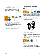
Clean Spray Gun

, page 16.

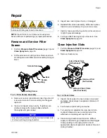
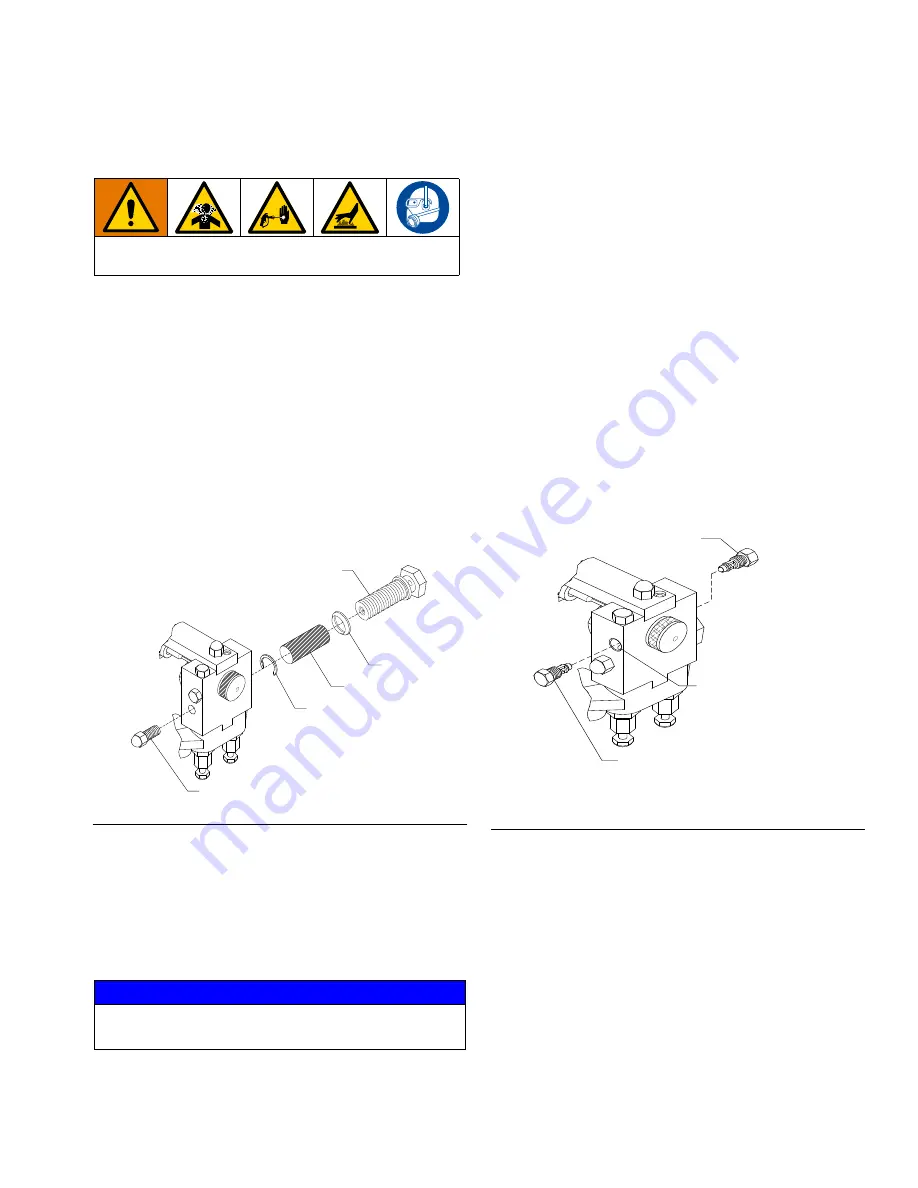
2. Unthread screen mounting screw. Remove screen 

mounting screw and filter screen assembly from gun 
block.

3. Remove screen screw retainer (snap ring at end of 

screw) and screen. If screen is dirty and clogged, 
replace it.

4. Clean and inspect screen cavity. If particles are 

visible, remove with cleanout drills and flush 
thoroughly with gun cleaner.

5. Inspect seal, and replace if worn or damaged.

6. Reinstall filter screen assembly. With seal in place, 

install screen and retainer clip-on screen screw. 

7. Install screen assembly to gun block. Ensure screw 

is tight to prevent leakage.

8. Flush gun after cleaning cavity and screen. See 

Clean Spray Gun

, page 16.

Clean Injection Slots

1. Perform 

Pressure Relief Procedure

 (page 13) and 

Clean Spray Gun

, page 16.

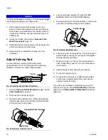
2. Remove check valves.

3. Inspect check valves to ensure sleeve is secured, 

and place check valves in separate containers of 
gun cleaner.

4. Flush cleanout ports with gun cleaner.

5. Turn valving rod adjustment screw one full turn 

counterclockwise to ensure valving rod will be 
withdrawn completely past injection slot.

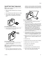
6. Clean mixing chamber injection slots. With air 

supply connected to gun, depress and hold trigger 
to keep valving rod in open position. Insert 
appropriate cleanout spade into cleanout hole and 
mixing chamber.

Shut down proportioner and allow chemicals to cool 
before performing any repair procedures.

F

IG

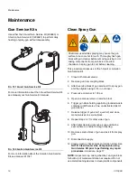
. 17 Filter Screen Assembly

NOTICE

Any remaining material in cavity on down stream side 
of screen will clog mixing chamber.

Screen Screw

Seal

Screen

Snap Ring

Mounting Screw

F

IG

. 18 Check Valves

A-Iso Check Valve
(tall hexhead)

Clean-out Port

(both sides)

R-Resin Check Valve

(short hexhead)

Summary of Contents for D-55

Page 1: ... use with non flammable polyurethane foams For professional use only 1000 psi 7 MPa 70 bar Maximum Working Pressure Important Safety Instructions Read all warnings and instructions in this manual before using the equipment Save these instructions ...

Page 2: ...rew 11 Air Cap Adjustment Valve 11 Felt Wiper 11 Initial Set Up 12 Daily Start Up 12 Daily Shutdown 13 Pressure Relief Procedure 13 Spray Pattern Adjustment 14 Maintenance 16 Gun Service Kits 16 Clean Spray Gun 16 Repair 17 Remove and Service Filter Screen 17 Clean Injection Slots 17 Adjust Valving Rod 18 Remove Fluid Head Component 19 Install Fluid Head Component 21 Parts 22 Model D Spray Gun Ass...

Page 3: ...authority Protective eyewear and hearing protection TOXIC FLUID OR FUMES HAZARD Toxic fluids or fumes can cause serious injury or death if splashed in the eyes or on skin inhaled or swallowed Read Safety Data Sheets SDSs for handling instructions and to know the specific hazards of the fluids you are using including the effects of long term exposure When spraying servicing equipment or when in the...

Page 4: ...ARD Misuse can cause death or serious injury Do not operate the unit when fatigued or under the influence of drugs or alcohol Do not exceed the maximum working pressure or temperature rating of the lowest rated system component See in all equipment manuals Use fluids and solvents that are compatible with equipment wetted parts See in all equipment manuals Read fluid and solvent manufacturer s warn...

Page 5: ...cedure when you stop spraying dispensing and before cleaning checking or servicing equipment Tighten all fluid connections before operating the equipment Check hoses tubes and couplings daily Replace worn or damaged parts immediately BURN HAZARD Equipment surfaces and fluid that is heated can become very hot during operation To avoid severe burns Do not touch hot fluid or equipment WARNING ...

Page 6: ...ry protection Always wear a properly fitting respirator which may include a supplied air respirator Ventilate the work area according to instructions in the fluid manufacturer s SDSs Avoid all skin contact with isocyanates Everyone in the work area must wear chemically impermeable gloves protective clothing and foot coverings as recommended by the fluid manufacturer and local regulatory authority ...

Page 7: ... component B wetted parts Never use solvent on one side if it has been contaminated from the other side NOTICE Partially cured ISO will reduce performance and the life of all wetted parts Always use a sealed container with a desiccant dryer in the vent or a nitrogen atmosphere Never store ISO in an open container Keep the ISO pump wet cup or reservoir if installed filled with appropriate lubricant...

Page 8: ... D Spray Gun FIG 1 Major Components Spring Retainer Case Valving Rod Closure Spring Valving Rod Positioner Valving Rod Adjustment Screw Valving Rod Stop Bar Valving Rod Piston Rod Trigger Air Cap Adjustment Valve Gun Block Coupling Block Coupling Block Mounting Screw ...

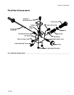
Page 9: ...Fluid Head Components Coupling Block Gaskets Air Cap Mixing Chamber Case Snap Ring Screen Seal A Iso Check Valve Screen Screw Gun Block Mounting Screw O Ring Closure Screw Valving Rod Assembly Felt Wiper Retainer Gun Block R Resin Check Valve Screen Mounting Screw ...

Page 10: ...ut 2 Close manual valves by turning fully clockwise Remove Coupling Block 1 Disconnect air hose 2 Close both manual valves 3 Remove coupling block mounting screw FIG 3 4 Separate coupling block from gun Do not lose gaskets 5 Use gun cleaner to wipe clean mating surface of gun block and coupling block Cover exposed opening with grease To prevent accidental gun operation always disconnect air supply...

Page 11: ...cally and tighten as required to prevent screw from slipping during operation Air Cap Adjustment Valve Use to control amount of air that passes through air cap and over mixing chamber tip Airflow helps keep tip free of sprayed chemical Too much air may distort spray pattern and create overspread Too little air will not properly clean end of valving rod To open valve turn knob approximately 1 8 tur...

Page 12: ...ner b Open each manual valve to allow trapped air to escape Bleed each side until chemical is free of air c Close both manual valves 9 Use clean cloth soaked in gun cleaner to wipe clean coupling block and its mating surfaces NOTE To avoid accumulation of dirt and other contaminants do not apply grease to mating surfaces of coupling block 10 Install coupling block to gun block 11 Proceed with Dail...

Page 13: ...dure whenever you see this symbol 1 Close both manual valves 2 Trigger gun once onto waste area to relieve fluid pressure in front end of gun 3 Disconnect gun air supply Air Hose Connection page 11 4 If gun is removed from coupling block follow Clean Spray Gun page 16 This equipment stays pressurized until pressure is manually relieved To help prevent serious injury from pressurized fluid such as ...

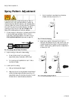
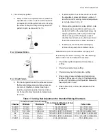
Page 14: ... from retainer case by 1 4 turn increments in counterclockwise direction c Point of valving is reached when chemical stream mists as shown in FIG 11 4 Adjust spray pattern Note position of notch in hexhead of adjustment screw then back screw out counterclockwise the number of turns specified in Table 1 Notice spray pattern opens as adjustment is made FIG 12 This adjustment may create a large mass ...

Page 15: ...ush e If buildup recurs shortly after cleaning tip remove air cap and ensure inside is clean Reinstall air cap and ensure airflow is properly set If no buildup occurred on air cap check the following items in this order and readjust if necessary Check Valving Rod Adjustment Screw Sleeve setting Check hose temperature setting Check primary heater temperature setting Ensure spray pressures between c...

Page 16: ...nobstructed mist of gun cleaner 7 Release trigger of gun and 1 quart kit and close manual valves on service block 8 Repeat steps 5 7 for other side of gun 9 After initial cleaning remove air cap and flush a second time to ensure thorough cleaning 10 Remove service block of gun service kit from spray gun 11 Disconnect air supply 12 Clean screens check valves and screen screw See NOTE Clean Center L...

Page 17: ...y and screen See Clean Spray Gun page 16 Clean Injection Slots 1 Perform Pressure Relief Procedure page 13 and Clean Spray Gun page 16 2 Remove check valves 3 Inspect check valves to ensure sleeve is secured and place check valves in separate containers of gun cleaner 4 Flush cleanout ports with gun cleaner 5 Turn valving rod adjustment screw one full turn counterclockwise to ensure valving rod wi...

Page 18: ... air cylinder 4 Loosen felt wiper retainer 2 3 turns DO NOT REMOVE THE FELT WIPER RETAINER 5 Remove valving rod Push back firmly on piston rod until end of Stop Bar emerges from cylinder 6 Loosen stop bar from positioner Turn positioner to adjust length of valving rod as required Retighten stop bar against positioner 7 Replace valving rod spring and spring retainer case Grasp firmly push in and tu...

Page 19: ...wiper Place wiper assembly in gun cleaner 11 Remove mixing chamber Hold gun block in one hand with chamber tip pointing into your palm Insert mixing chamber knockout tool into rear of gun block and tap with hammer until chamber ejects Place chamber in gun cleaner 12 Remove closure screw in top of gun block Place screw in gun cleaner and clean entire gun using appropriate cleanout tools and brass b...

Page 20: ...k and keeping pressure on head of check valve slice check valve sleeve with razor knife at a 10 15 degree angle relative to the plane of removal block Remove check valve from block and peel sleeve off If check valve sleeve remains in gun block after removing check valve use extractor tool to remove sleeve Insert threaded end of tool into cleanout port and while pressing tool into gun block turn it...

Page 21: ... frame 8 Install valving rod assembly If using new felt wiper push valving rod through felt with retainer case off chamber Remove felt wiper and any felt buildup on tip of rod Install wiper hand tighten into rear of chamber in gun block Then insert valving rod through piston in air cylinder guiding it through center of felt wiper retainer Use firm pressure to carefully push valving rod into mixing...

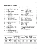
Page 22: ...Parts 22 311320K Parts Model D Spray Gun Assembly 12 11 10 28 22 2 20 17 18 5 19 25 31 24 23 7 35 32 38 21 9 6 2 26 8 1 15 29 30 4 33 4 14 27 13 34 37 36 16 4 3 39 ...

Page 23: ... mesh pack of 50 19 295595 Snap ring 1 20 296624 Kit gun block screen screw includes U V W 1 21 296611 Felt wiper assembly includes retainer wiper washer pack of 5 297139 Felt wiper pack of 15 and retainer washers pack of 3 22 111450 O ring 1 23 296625 Coupling block gasket pack of 2 24 296121 D gun block complete includes G AA AP 1 25 Mixing chamber includes Y see Table 1 1 26 295590 Gun frame 1 ...

Page 24: ...ithout blowing away freshly applied foam Pattern diameter is approximately 4 in with gun 4 in 10 2 cm distance from target Output is approximately 2 to 3 1 4 pounds min 9 to 1 5 kg min 46 Size 296595 N 810 296585 L 810 296591 L 810 LM For the same uses as above These chambers have an increased output of approximately 3 to 4 1 2 pounds min 1 4 to 2 0 kg min 55 Size 296597 N 296586 L 296592 L LM Des...

Page 25: ... and cards are available at no cost Ref Part Description Qty 1 107083 O ring fluoroelastomer 1 B2 295494 Pan head machine screw 8 32 x 3 16 in 1 3 295177 Front head blank 1 4 296627 U cup pack of 5 5 296628 U cup pack of 5 6 295178 Cylinder 1 7 296631 Wear ring 1 8 295179 Buttonhead cap screw 3 9 295484 Piston assembly 1 10 295492 Label warning 1 2 1 3 4 5 9 6 7 10 8 ...

Page 26: ... 295888 R swivel fitting 1 3 295889 A swivel fitting 1 4 296626 Manual valve assembly pack of 2 5 295619 Mounting screw 15 16 in 1 6 295693 Flush seal pipe plug 1 36 in 2 7 295886 Coupling block 1 Ref Part Description Qty 8 295889 A swivel fitting 2 9 296626 Manual valve assembly pack of 2 10 295619 Mounting screw 1 11 295693 Pipe plug 2 12 112307 Street elbow 2 13 295886 Coupling block 1 14 29588...

Page 27: ...lb min 7 3 kg min Minimum Output flow rate 2 lb min 0 9 kg min A Component ISO Inlet Size 5 JIC 1 2 20 UNF R Component Resin Inlet Size 6 JIC 9 16 18 UNF Length 9 25 in 24 cm Height 8 in 20 cm Width without coupling block 2 4 in 6 cm Weight 3 lb 1 4 kg Wetted Parts Stainless steel carbon steel brass nylon acetal PTFE Notes Theoretical actual results will vary with operating conditions All trademar...

Page 28: ...material or workmanship repairs will be made at a reasonable charge which charges may include the costs of parts labor and transportation THIS WARRANTY IS EXCLUSIVE AND IS IN LIEU OF ANY OTHER WARRANTIES EXPRESS OR IMPLIED INCLUDING BUT NOT LIMITED TO WARRANTY OF MERCHANTABILITY OR WARRANTY OF FITNESS FOR A PARTICULAR PURPOSE Graco s sole obligation and buyer s sole remedy for any breach of warran...

Reviews: