10
308152
Installation
(HYDRAULIC-POWERED PUMPS)
NOTE: Reference numbers and letters in parentheses
in the text refer to the callouts in the figures and the
parts drawing.
NOTE: Accessories are available from your Graco
distributor. If you supply your own accessories, be sure
they are adequately sized and pressure-rated to meet
the system’s requirements.
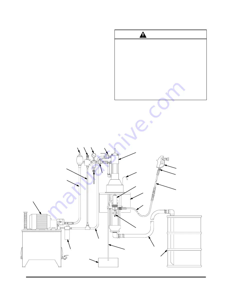
Fig. 4 is only a guide for selecting and installing sys-
tem components and accessories. Contact your Graco
distributor for assistance in designing a system to suit
your particular needs.
CAUTION
Keep the hydraulic supply system clean at all times.
Be sure that all hydraulic fluid lines are absolutely
clean. Blow out the lines with air and flush thoroughly
with solvent before connecting to the hydraulic
motor, to avoid introducing harmful contaminants into
the motor. Plug the hydraulic lines immediately when
they are disconnected.
Do not exceed 37.8 liter/min (10 gpm) hydraulic oil
volume to the motor, to avoid stalling the pump.
For optimum pump performance, keep the tempera-
ture of the hydraulic oil below 54
_
C (130
_
F).
Fig. 4
0627B
KEY
A
Pump
B
Wall Bracket
C
Hydraulic Supply Line
D
Hydraulic Return Line
E
Drain Line (from pressure reducing valve)
F
Pressure Gauge
G
Flow Control Valve
H
Pressure Reducing Valve
J
Accumulator
K
Drain Line (from motor drip pan)
L
Fluid Filter
M
Fluid Drain Valve (required)
N
Electrically Conductive
Fluid Supply Hose
P
Fluid Whip Hose
R
Gun/Valve Swivel
S
Airless Spray Gun or Dispensing Valve
T
Drum Suction Kit
U
Hydraulic Supply Line Shutoff Valve
V
Hydraulic Return Line Shutoff Valve
Y
Ground Wire (required, see page 7 for
installation instructions)
AA Hydraulic Return Line Filter
A
B
D
E
F
G
H
J
K
M
N
P
Y
200 LITER
(55 GAL.)
DRUM
L
R
S
T
U
C
V
HYDRAULIC
POWER SUPPLY
DRAINAGE
CONTAINER
AA
TYPICAL INSTALLATION
Summary of Contents for Dura-Flo 2400
Page 6: ...6 308152 Notes ...
Page 12: ...12 308152 Notes ...


