background image

308152

5

WARNING

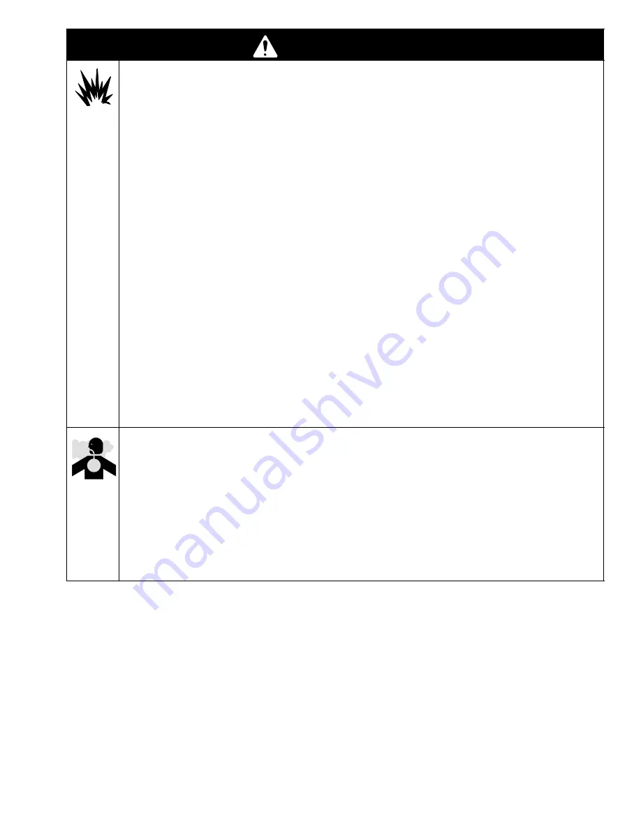
FIRE AND EXPLOSION HAZARD

Improper grounding, poor ventilation, open flames, or sparks can cause a hazardous condition and
result in a fire or explosion and serious injury.

D

Ground the equipment and the object being sprayed. Refer to Grounding  on page 7.

D

If there is any static sparking or you feel an electric shock while using this equipment, stop spray-
ing immediately.
 Do not use the equipment until you identify and correct the problem.

D

Provide fresh air ventilation to avoid the buildup of flammable fumes from solvents or the fluid
being sprayed.

D

Eliminate all ignition sources such as pilot lights, cigarettes, and plastic drop cloths (static arc
hazard). Do not plug or unplug power cords or turn lights on or off in the spray area.

D

Keep the spray area free of debris, including solvent, rags, and gasoline.

D

Electrically disconnect all equipment in the spray area.

D

Extinguish all open flames or pilot lights in the spray area.

D

Do not smoke in the spray area.

D

Do not turn on or off any light switch in the spray area while operating or if fumes are present.

D

Do not operate a gasoline engine in the spray area.

D

Keep a fire extinguisher in the working area.

TOXIC FLUID HAZARD

Hazardous fluid or toxic fumes can cause serious injury or death if splashed in the eyes or on the skin,
inhaled, or swallowed.

D

Know the specific hazards of the fluid you are using.

D

Store hazardous fluid in an approved container. Dispose of hazardous fluid according to all local,
state, and national guidelines.

D

Always wear protective eyewear, gloves, clothing, and respirator as recommended by the fluid and
solvent manufacturer.

Summary of Contents for Dura-Flo 2400

Page 1: ...er for abrasive coatings Instructions Parts List 308152Z1 Important Safety Instructions Read all warnings and instructions in this manual Save these instructions See page 2 for Model Numbers Maximum Working Pressures and Table of Contents Part No 222899 Shown 0566B ...

Page 2: ...r 249991 Series A 34 1 23 0 MPa 234 bar 3400 psi 0 7 MPa 7 bar 100 psi 249158 Series A Premier 249991 Series A 34 1 23 0 MPa 234 bar 3400 psi 0 7 MPa 7 bar 100 psi 253843 Series A Premier 249991 Series A 34 1 23 0 MPa 234 bar 3400 psi 0 7 MPa 7 bar 100 psi K This manual also covers displacement pumps 236226 222994 236230 and 222993 See pages 34 and 35 Table of Contents Warnings 3 Installation 7 Ai...

Page 3: ...ment Use only genuine Graco parts and accessories D Check equipment daily Repair or replace worn or damaged parts immediately D Do not exceed the maximum working pressure of the lowest rated system component Refer to the Technical Data section on page 36 for the maximum working pressure of this equipment D Use fluids and solvents which are compatible with the equipment wetted parts Refer to the Te...

Page 4: ...e the gun trigger safety operates before spraying D Lock the gun trigger safety when you stop spraying D Follow the Pressure Relief Procedure on page 13 whenever you are instructed to relieve pres sure stop spraying clean check or service the equipment and install or clean the spray tip D Tighten all fluid connections before operating the equipment D Check the hoses tubes and couplings daily Repla...

Page 5: ... turn lights on or off in the spray area D Keep the spray area free of debris including solvent rags and gasoline D Electrically disconnect all equipment in the spray area D Extinguish all open flames or pilot lights in the spray area D Do not smoke in the spray area D Do not turn on or off any light switch in the spray area while operating or if fumes are present D Do not operate a gasoline engin...

Page 6: ...6 308152 Notes ...

Page 7: ...ensure grounding continuity Check the electrical resistance of your hoses at least once a week If the total resistance to ground exceeds 29 megohms replace the hose immediately NOTE Use a meter that is capable of measuring resistance at this level 3 Air compressor or hydraulic power supply follow manufacturer s recommendations 4 Spray gun ground through connection to a prop erly grounded fluid hos...

Page 8: ...sistance in designing a system to suit your particular needs Fig 3 KEY A Pump B Wall Bracket C Pump Runaway Valve D Air Line Lubricator E Bleed Type Master Air Valve required for pump F Pump Air Regulator G Air Manifold H Electrically Conductive Air Supply Hose J Air Line Filter K Bleed Type Master Air Valve for accessories L Fluid Filter M Fluid Drain Valve required N Electrically Conductive Flui...

Page 9: ...ries in the order shown in Fig 3 using adapters as necessary D An air line lubricator D provides automatic air motor lubrication D A bleed type master air valve E is required in your system to relieve air trapped between it and the air motor when the valve is closed see the WARNING at left Be sure the bleed valve is easily accessible from the pump and is located down stream from the air regulator ...

Page 10: ...ants into the motor Plug the hydraulic lines immediately when they are disconnected Do not exceed 37 8 liter min 10 gpm hydraulic oil volume to the motor to avoid stalling the pump For optimum pump performance keep the tempera ture of the hydraulic oil below 54_ C 130_ F Fig 4 0627B KEY A Pump B Wall Bracket C Hydraulic Supply Line D Hydraulic Return Line E Drain Line from pressure reducing valve ...

Page 11: ... avoid overpressurizing the motor or displacement pump and a pressure and temperature compensated flow control valve G to prevent the motor from running too fast and possibly damaging itself D A pressure reducing valve H with a drain line E run directly to the hydraulic return line D D An accumulator J to reduce the hammering effect caused by the motor reversing direction On the hydraulic return l...

Page 12: ...12 308152 Notes ...

Page 13: ...the gun to relieve pressure 6 Lock the gun trigger safety 7 Open the drain valve required in your system having a container ready to catch the drainage 8 Leave the drain valve open until you are ready to spray again If you suspect that the spray tip or hose is completely clogged or that pressure has not been fully relieved after following the steps above very slowly loosen the tip guard retaining ...

Page 14: ...bleed er valve plug 35 slightly Use the bleed hole on the underside of the valve body 34 as a priming valve until the fluid appears at the hole See Fig 5 Close the plug 35 NOTE When changing fluid containers with the hose and gun already primed open the bleeder valve plug 35 to help prime the pump and vent air before it enters the hose Close the plug when all air is elimi nated CAUTION Do not allo...

Page 15: ...entire system and flush ing pails are properly grounded Refer to Grounding on page 7 Flush with a fluid that is compatible with the fluid you are pumping and with the wetted parts in your system Check with your fluid manufacturer or supplier for rec ommended flushing fluids and flushing frequency Al ways flush the pump before fluid dries on the displace ment rod WARNING To reduce the risk of serio...

Page 16: ...plug 35 NOTE When changing fluid containers with the hose and gun already primed open the bleeder valve plug 35 to help prime the pump and vent air before it enters the hose Close the plug when all air is elimi nated CAUTION Do not allow the pump to run dry It will quickly accelerate to a high speed causing damage If the pump is running too fast stop it immediately and check the fluid supply If th...

Page 17: ...he entire system and flush ing pails are properly grounded Refer to Grounding on page 7 Flush with a fluid that is compatible with the fluid you are pumping and with the wetted parts in your system Check with your fluid manufacturer or supplier for rec ommended flushing fluids and flushing frequency Al ways flush the pump before fluid dries on the displace ment rod WARNING To reduce the risk of se...

Page 18: ... Open clear use hose with larger ID Bleeder valve open Close Fluid too heavy for pump priming Use bleeder valve see pages 14 and 16 use ram Worn packings in displacement pump Replace packings Pump operates but output low on down Held open or worn intake valve Clear valve service output low on down stroke Fluid too heavy for pump priming Use bleeder valve see pages 14 and 16 use ram Pump operates b...

Page 19: ...ht exceeds 550 lb 250 kg 4 Disconnect the displacement pump 105 from the motor 101 as follows Be sure to note the relative position of the pump s fluid outlet to the air or hydraulic inlet of the motor If the motor does not require servicing leave it attached to its mounting CAUTION Be sure to use at least two people when lifting mov ing or disconnecting the pump This pump is too heavy for one per...

Page 20: ...displacement pump while another reconnects it to the motor see the CAUTION at left Orient the pump s fluid outlet to the air or hydraulic inlet as was noted in step 4 under Disconnecting the Displacement Pump Position the displacement pump 105 on the tie rods 107 See Fig 6 2 Screw the nuts 106 onto the tie rods 107 and torque as noted in Fig 6 3 Place the coupling nut 103 on the displacement rod 1...

Page 21: ...Torque to 128 156 NSm 95 115 ft lb Torque to 81 89 NSm 60 66 ft lb Square hole is for use with torque wrench Torque to 129 142 NSm 95 105 ft lb Torque to 312 340 NSm 230 250 ft lb 2 3 5 6 3 108 101 106 1 0567B 105 4 104 107 102 103 1 1 2 3 4 105 104 108 4 2 5 5 6 4 101 1 01397C 3 102 103 3 106 107 6 Apply LoctiteR 2760t or equivalent to threads 7 7 ...

Page 22: ...alve body 34 Clean the valve threads and the bleed hole It is not necessary to remove the valve body from the pump outlet housing 19 7 Stand the cylinder 7 upright on a wooden block Using a rubber mallet or an arbor press drive the displacement rod 1 and piston assembly down into the cylinder as far as possible then place the cylinder on its side and continue to drive the rod out the bottom until ...

Page 23: ...308152 23 Service Fig 7 10 1 9 10 7 17 15 16 14 19 35 5 4 20 3 12 6 6 A B T P 8 36 10 0421A Included only on Displacement Pumps 222803 222994 and 241648 with stainless steel cap screws 20 ...

Page 24: ...ve the rod into the cylinder and be sure to place the cylinder on a soft block of wood Never use a hammer to drive the rod 5 Lubricate the o ring 8 and seal 6 Install the o ring on the intake seat housing 15 Install the intake seat housing 15 intake ball 16 ball guide 14 and seal 6 in the intake housing 17 Set the intake housing all the way into the vise 6 Place the cylinder 7 on the intake housin...

Page 25: ...thread lubricant Use arbor press to drive into cylinder 7 Unscrew valve plug from valve housing and clean Included only on Displacement Pumps 222803 222994 and 241648 with stainless steel cap screws 20 11 Torque to 31 37 NSm 23 27 ft lb 1 9 10 7 17 15 16 14 19 35 5 4 20 3 12 6 6 A B 1 6 3 6 6 7 4 5 3 6 9 2 8 T P 8 10 36 0421A 11 Torque to 60 70 NSm 45 55 ft lbs For displacement pump 241648 only li...

Page 26: ...PTER connecting rod 1 103 184096 NUT coupling 1 104 184278 WRENCH packing nut 1 105 222803 PUMP displacement See pages 30 32 for parts 1 106 106166 NUT hex M16 x 2 0 3 107 184452 ROD tie 265 mm 10 43 in shoulder to shoulder carbon steel 3 108 184130 COLLAR coupling 2 For applications requiring stainless steel tie rods order Connection Kit 222913 0570B 101 105 104 106 108 102 107 103 ...

Page 27: ...s requiring stainless steel tie rods order Connection Kit 222913 Part No 222898 Pump Series B 20 1 Ratio with Quiet King Air Motor Ref No Part No Description Qty 101 220106 AIR MOTOR King quiet See manual 309348 for parts 1 102 184451 ADAPTER connecting rod 1 103 184096 NUT coupling 1 104 184278 WRENCH packing nut 1 105 222803 PUMP displacement See pages 30 32 for parts 1 106 106166 NUT hex M16 x ...

Page 28: ...IR MOTOR Premier See manual 308213 for parts 1 102 184582 ADAPTER connecting rod 1 103 184096 NUT coupling 1 104 184278 WRENCH packing nut 1 105 222803 PUMP displacement used on Part No 222943 See pages 30 32 for parts 1 15F298 PUMP displacement used on Part No 249158 See pages 30 32 for parts 1 249991 PUMP displacement used on Part No 253843 and 249157 See pages 30 32 for parts 1 106 106166 NUT h...

Page 29: ...C MOTOR Viscount See manual 307158 for parts 1 102 184595 ADAPTER connecting rod 1 103 184096 NUT coupling 1 104 184278 WRENCH packing nut 1 105 222803 PUMP displacement See pages 30 32 for parts 1 106 106166 NUT hex M16 x 2 0 3 107 184596 ROD tie 315 mm 12 40 in shoulder to shoulder 3 108 184130 COLLAR coupling 2 These parts are included in Connection Kit 222976 ...

Page 30: ...splacement Pump Parts NOTE The parts listed on this page are common to all displacement pumps covered in this manual The pumps use different packing configurations Pump Models 222803 222994 241648 15F298 and 249991 use stainless steel cap screws with washers Models 222993 236226 and 236230 use carbon steel cap screws without a washer Refer to pages 32 through 35 for the different pump configuratio...

Page 31: ...991 only 1 12 222802 HOUSING seat piston valve stainless steel w tungsten carbide seat 1 253741 HOUSING valve seat used on 249991 only 1 14 184282 GUIDE ball intake stainless steel 1 15 222838 HOUSING seat intake valve stainless steel w tungsten carbide seat 1 253742 HOUSING valve seat used on 249991 only 1 16 110294 BALL intake stainless steel 2 in 50 8 mm dia 1 15C868 BALL intake silicon nitride...

Page 32: ... THROAT PACKINGS LIPS FACE DOWN PISTON PACKINGS LIPS FACE UP 0805 0806 LUBRICATE PACKINGS 11 32 18 25 26 27 28 13 Displacement Pump 15F298 Series A UHMWPE and Leather Packings NOTE For this pump only limit packing nut torque to 27 40 NSm 20 30 ft lb Ref Part No No Description Qty 11 109266 V PACKING piston UHMWPE 3 13 184236 GLAND male piston stainless steel 1 20 109470 SCREW cap hex hd 5 8 11 unc...

Page 33: ...GS LIPS FACE UP 0805 0806 18 32 25 27 28 13 LUBRICATE PACKINGS Optional Displacement Pumps Displacement Pump 241648 Series A UHMWPE and Carbon Filled PTFE Packings with Stainless Steel Cap Screws Carbon filled PTFE for use with water up to 60_ C 140_ F NOTE For this pump only limit packing nut torque to 27 40 NSm 20 30 ft lb Ref Part No No Description Qty 11 109266 V PACKING piston UHMWPE 3 13 184...

Page 34: ...5 26 27 28 13 Wetted Parts Chrome Zinc and Electroless Nickel Plating 304 329 and 17 4 PH Grades of Stainless Steel Tungsten Carbide acetal PTFE UHMWPE Displacement Pump 222994 Series A PTFE Packings with Stainless Steel Cap Screws Ref Part No No Description Qty 13 184236 GLAND male piston stainless steel 1 18 109316 V PACKING piston PTFE 5 20 109470 SCREW cap hex hd 5 811 unc 2A x 12 in 305 mm st...

Page 35: ...E 1 Ref Part No No Description Qty 20 109203 SCREW cap hex hd 5 8 11 unc 2A x 12 in 305 mm carbon steel see page 30 6 25 184185 GLAND female throat stainless steel 1 27 109315 V PACKING throat PTFE 1 28 184235 GLAND male throat stainless steel 1 29 184316 V PACKING piston leather 4 30 184315 V PACKING throat leather 4 32 184186 GLAND female piston stainless steel 1 The replacements for these parts...

Page 36: ...aximum pump operating temperature 82_ C 180_ F Air inlet size 3 4 npsm f Fluid inlet size 2 in npt f Fluid outlet size 1 1 2 npt m Weight approx 61 kg 134 lb Wetted parts 304 329 and 17 4 PH Grades of Stainless Steel Tungsten Carbide acetal PTFE Ultra High Molecular Weight Polyethylene Sound Pressure Levels dBa measured at 1 meter from unit Input Air Pressures at 15 cycles per minute Air Motor 0 2...

Page 37: ...rt 2 Read vertical line up to intersection with selected air consumption curve dashes Follow left to scale to read air consumption A 0 7 MPa 7 bar 100 psi air pressure B 0 5 MPa 4 9 bar 70 psi air pressure C 0 3 MPa 2 8 bar 40 psi air pressure Performance Charts Standard Bulldog Pumps 0 200 400 600 800 1000 0 2 4 6 8 10 Fluid Outlet Pressure 13 26 39 psi MPa bar cycles per minute gpm liters minute...

Page 38: ... 3 72 in 2 Maximum pump operating temperature 82_ C 180_ F Air inlet size 3 4 npsm f Fluid inlet size 2 in npt f Fluid outlet size 1 1 2 in npt m Weight approx 69 kg 162 lb Wetted parts 304 329 and 17 4 PH Grades of Stainless Steel Tungsten Carbide acetal PTFE Ultra High Molecular Weight Polyethylene Sound Pressure Levels dBa measured at 1 meter from unit Input Air Pressures at 15 cycles per minut...

Page 39: ... 3 78 2 52 Test Fluid No 10 Weight Oil 2 1 21 38 0 65 52 15 2 1 26 6 30 8 4 84 4 2 42 30 4 52 30 4 38 0 65 10 5 105 5 04 To find Fluid Outlet Pressure psi MPa bar at a specific fluid flow lpm gpm and operating air pressure psi MPa bar 1 Locate desired flow along bottom of chart 2 Follow vertical line up to intersection with selected fluid outlet pressure curve black Follow left to scale to read fl...

Page 40: ...id outlet size 1 1 2 in npt m or M42 x 2 0 Part No 241648 only Weight approx 109 kg 240 lb Wetted parts 304 329 and 17 4 PH Grades of Stainless Steel Tungsten Carbide acetal PTFE Ultra High Molecular Weight Polyethylene Carbon Filled PTFE Part No 241648 only Wetted parts LASD Pumps 249157 249158 and 253843 304 329 and 17 4 PH Grades of Stainless Steel Silicone Nitride Leather acetal PTFE UHMWPE Tu...

Page 41: ...e up to intersection with selected air consumption curve dashes Follow left to scale to read air consumption A 0 7 MPa 7 bar 100 psi air pressure B 0 5 MPa 4 9 bar 70 psi air pressure C 0 3 MPa 2 8 bar 40 psi air pressure Performance Charts Premier Pumps 0 500 1000 1500 2000 2500 3000 3500 0 2 4 6 8 10 Fluid Outlet Pressure 13 26 39 psi MPa bar cycles per minute gpm liters minute 22 8 7 6 15 2 FLU...

Page 42: ...si Pump cycles per 3 8 liters 1 gal 6 5 Fluid flow at 60 cpm 34 9 liters min 9 2 gpm Hydraulic motor piston effective area 31 6 cm2 4 9 in 2 Stroke length 120 mm 4 75 in Displacement pump effective area 24 cm2 3 72 in 2 Maximum pump operating temperature 65 5_ C 150_ F Hydraulic oil supply size 3 4 npsm f Hydraulic oil return size 1 in npt Fluid inlet size 2 in npt f Fluid outlet size 1 1 2 in npt...

Page 43: ...al line up to intersection with selected hydraulic con sumption curve dashes Follow left to scale to read oil consump tion A 10 5 MPa 105 bar 1500 psi hydraulic oil pressure B 7 5 MPa 74 bar 1050 psi hydraulic pressure C 4 2 MPa 42 bar 600 psi hydraulic pressure Performance Charts Viscount Pump Test Fluid No 10 Weight Oil 0 400 800 1200 1600 2000 0 2 4 6 8 10 Fluid Outlet Pressure 13 26 39 psi MPa...

Page 44: ...mm 11 73 in 222899 1226 mm 48 25 in 642 6 mm 25 3 in 583 0 mm 22 95 in 298 0 mm 11 73 in 222898 1235 mm 48 63 in 642 6 mm 25 3 in 592 5 mm 23 33 in 298 0 mm 11 73 in 222943 249157 249158 253744 1160 0 mm 45 7 in 759 0 mm 29 9 in 401 0 mm 15 79 in 413 0 mm 16 3 in 222900 1264 8 mm 49 8 in 642 6 mm 25 3 in 622 2 mm 24 5 in 298 0 mm 11 73 in ...

Page 45: ... 1 mm 0 437 in DIA 4 94 28 mm 3 712 in 101 6 mm 4 0 in 50 8 mm 2 0 in 0653 Premier Pumps King Bulldog and Viscount Pumps 06555 67 5 mm 2 7 in 135 0 mm 5 3 in 50 7 mm 2 0 in 101 5 mm 4 0 in 116 9 mm 4 6 in 87 9 mm 3 5 in Three M16 x 2 0 Holes Three 3 8 16 Mounting Studs ...

Page 46: ...medy including but not limited to incidental or consequential damages for lost profits lost sales injury to person or property or any other incidental or consequential loss shall be available Any action for breach of warranty must be brought within two 2 years of the date of sale Graco makes no warranty and disclaims all implied warranties of merchantability and fitness for a particular purpose in...

Reviews: