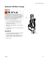
Hydraulic Pump
3A2247A
13
9.
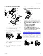
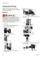
Remove hose (276) from elbow (226). Remove
elbow (226) from hydraulic pump (220).
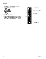
10. Remove hydraulic hose (288) from reservoir cover
(209).
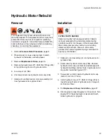
11. Remove eight screws (212) reservoir cover (209) fil-
ter assembly (206) and gasket (203).
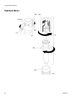
12. Remove four screws (277) and hydraulic pump
(220) from reservoir cover (209).
Installation
1.
Install hydraulic pump (220) to reservoir cover (209)
with four screws (277) (ensure o-rings 210 and 211
are in place); torque 90 - 110 in-lb (10 - 12 N•m).
2.
Install gasket (203) filter assembly (206) and
reservoir cover (209) with eight screws (212).
Torque 110 - 120 in-lb (12 - 14 N•m).
3.
Install hydraulic hose (288) to reservoir cover (209).
4.
Install elbow (226) in hydraulic pump (220). Install
hose (276) in elbow (226). Torque to 15 ft-lb (20.3
N•m).
5.
Install elbow (221); torque to 15 ft-lb (20.3 N•m).
6.
Install case drain tube (225); torque to 15 ft-lb (20.3
N•m).
7.
Install fan pulley (96) with two set screws (197).
8.
Raise electric motor (or gas engine) and install belt
(44).
9.
Install belt guard (117) with screw (172) and nut
(173).
10. Install drain plug (202). Install oil filter (227); tighten
3/4 turn after gasket contacts base. Fill hydraulic
pump with Graco hydraulic oil, page 6, through
elbow (221) port until full. Fill reservoir with remain-
ing hydraulic oil.
11. Start up and allow pump to operate at low pressure
for approximately 5 minutes to purge all air.
12. Check oil hydraulic oil and top off, if required.
ti18354a
220
226
276
ti18355a
209
288
ti18356a
212
209
206
203
ti18357a
209
220
277


