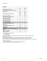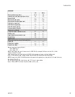
Electric Motor
3A2247A
21
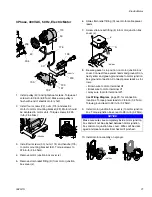
3 Phase, 400 VAC, 50 Hz, Electric Motor
1.
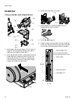
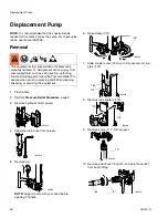
Install pulley (43) and tighten set screws. Torque set
screws to 60 in-lb (6.8 N•m). Make sure pulley is
flush with end of electric motor shaft.
2.
Install four screws (23), nuts (174) and electric
motor to motor mounting bracket (99). Motor should
be centered in motor slots. Torque screws to 225
in-lb (25.4 N•m).
3.
Install four screws (30), nuts (174) and handle (175)
to motor mounting bracket (99). Torque screws to
225 in-lb (25.4 N•m).
4.
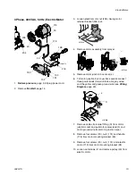
Remove motor junction box cover (J).
5.
Remove strain relief fitting (S) from motor junction
box cover (J).
6.
Slide strain relief fitting (S) over motor cable power
leads.
7.
Screw strain relief fitting (5) into motor junction box
cover (J).
8.
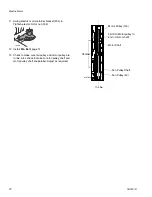
Be sure gasket is in position on motor junction box
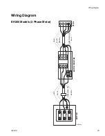
cover. Connect three power leads and ground. Con-
nect yellow and green ground wire to motor junction
box ground connection. Connect power leads as fol-
lows:
• Brown wire to motor terminal U1
• Black wire to motor terminal V1
• Grey wire to motor terminal W1
See
Wiring Diagram
, page 29, for connection
locations. Torque power leads to 28 in-lb (3.2 N•m).
Torque ground lead to 28 in-lb (3.2 N•m).
9.
Install motor junction box cover (J) to motor junction
box. Torque junction box cover to 28 in-lb (3.2 N•m).
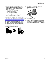
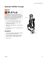
10. Install motor assembly on sprayer.
204
205
43
30
119
175
30
190
192
191
193
ti18617a
200
198
ti18696a
NOTICE
Make sure wires are completely inside motor junction
box and will not be pinched between motor junction
box and motor junction box cover. Wires will be dam-
aged and create an electrical hazard if pinched.
ti18700a
S
J
ti18748a


