Control
Control
Control Board
Board
Board Replacement
Replacement
Replacement
(25C187)
(25C187)
(25C187)
NOTICE
NOTICE
NOTICE
To avoid damage to the electric components, wear
grounding strap (Graco Part No. 112190 – not
supplied) and ground appropriately.
Overview
Overview
Overview
The main control board assembly manages the
operation of the driver. It is permanently attached
to the electronics cover.
Tools
Tools
Tools Required
Required
Required
• 6 mm Hex Wrench
• Phillips Screwdriver (#1)
• Torque Wrench (15 ft-lb, 20 N
•
m)
Prepare
Prepare
Prepare Driver
Driver
Driver
1.
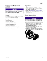
Remove power from the driver. Follow
appropriate lock-out/tag-out procedures. Wait
five minutes before servicing.
2.
Follow the
Pressure Relief Procedure, page 8
.
3.
Decouple the pump lower from the driver per the
system manual.
Disconnect
Disconnect
Disconnect Power
Power
Power Wires
Wires
Wires
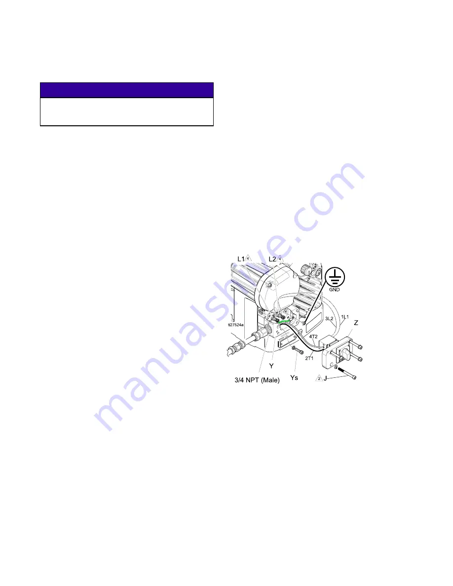
1.
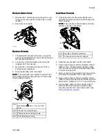
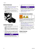
Remove the screws (J) and junction box cover
(Z) from the electrical junction box (Y). Remove
screw (Ys) and sleeve housing.
2.
Disconnect wires from terminal bushings L1 and
L2.
3.
Remove the ground lug and disconnect the green
ground wire.
4.
Disconnect wires from the opposite side of the
disconnect in terminals labeled 2T1 and 4T2.
14
3A5124B


