


Driver
Driver
Driver Operation
Operation
Operation
Pressure
Pressure
Pressure Control
Control
Control
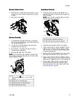
The driver will adjust the speed to maintain a constant
fluid pressure.
1.
Pull the Pressure Control Knob (N) out to set.
2.
Turn the Pressure Control Knob (N) fully
counterclockwise to 0.
3.
Turn the knob clockwise to increase the pressure,
or counterclockwise to decrease the pressure.
Push the knob in to lock.
Maintenance
Maintenance
Maintenance
Preventive
Preventive
Preventive Maintenance
Maintenance
Maintenance Schedule
Schedule
Schedule
The operating conditions of your particular system
determine how often maintenance is required.
Establish a preventive maintenance schedule by
recording when and what kind of maintenance is
needed, and then determine a regular schedule for
checking your system.
Change
Change
Change the
the
the Oil
Oil
Oil
NOTE:
NOTE:
NOTE: Change the oil after a break-in period of
200,000–300,000 cycles. After the break-in period,
change the oil once a year. Order two Silicone-Free
Synthetic ISO 220 EP Gear Oil (Graco Part No.
16W645).
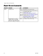
1.
Place a minimum 2 quart (1.9 liter) container
under the oil drain port. Remove the oil drain
plug (G). Allow all oil to drain from the driver.
2.
Reinstall the oil drain plug (G). Torque to 18–23
ft-lb (25–30 N•m).
NOTICE
NOTICE
NOTICE
Do not over-torque. The drain plug can
become stripped and damaged.
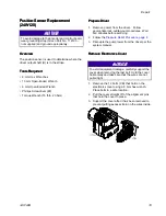
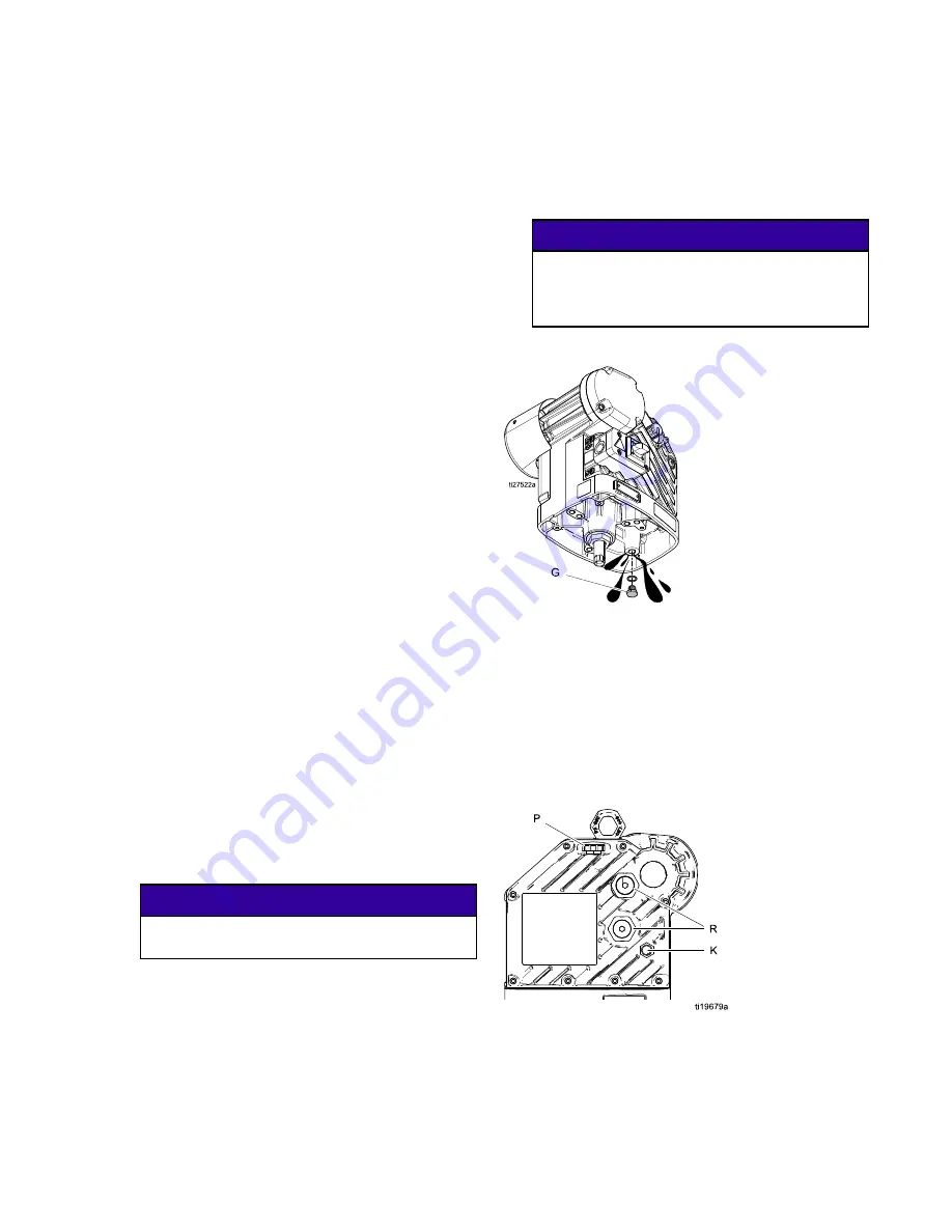
3.
Open the fill cap (P) and add Graco Part No.
16W645 Silicone-Free Synthetic ISO 220 EP
Gear Oil. Check the oil level in the sight glass (K).
Fill until the oil level is near the halfway point of
the sight glass. The oil capacity is approximately
1.–1.2 quarts (0.9–1.1 liters). Do
Do
Do not
not
not overfill.
overfill.
overfill.
NOTICE
NOTICE
NOTICE
Only use Graco GBL oil (Graco part number
16W645). Any other oil may not lubricate
properly and can cause damage to the drive
train.
4.
Reinstall the fill cap.
Check
Check
Check Oil
Oil
Oil Level
Level
Level
Check the oil level in the sight glass (K). The oil level
should be near the halfway point of the sight glass
when the unit is not running. If low, open the fill cap
(P) and add Graco Part No. 16W645 Silicone-Free
Synthetic ISO 220 EP Gear Oil as required. The oil
capacity is approximately 1.0–1.2 quarts (0.9–1.1
liters). Do
Do
Do not
not
not overfill.
overfill.
overfill.
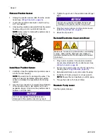
Bearing
Bearing
Bearing Pre
Pre
Pre---Load
Load
Load
The bearing pre-loads (R) are factory set and are not
user adjustable. Do not adjust the bearing pre-loads.
3A5124B
9


