background image

Setup

3A7467C

17

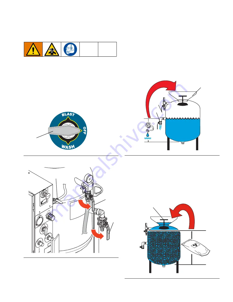
Fill Pot with Abrasive Media

1. Verify that the pot seal plunger (F) is in the DOWN 

position. If the plunger is in the up position, perform 
the 

Pressure Relief Procedure

 procedure, page 

19.

2. Verify that 

Installation

, page 12, is complete.

3. Close the rinse ball valve (X) and the abrasive ball 

valve (M).

4. Turn the selector valve (W) to OFF.

5. Open the pot dump valve (J).

6. Open the quick drain valve (ZL).

7. Prepare the pot to accept media:

-

To fill an empty pot:

 Fill approximately half the 

pot (E) with water, until the water drains from 
the quick drain valve (ZL). Shut the quick drain 
valve.

-

To refill the pot during operation:

 open the 

quick drain valve (ZL) to drain the water until the 
pot is approximately half full. Shut the quick 
drain valve.

8. Add abrasive media to the pot. 

NOTE:

 The media level should be a few inches below 

the pot seal plunger (F). Do not overfill the pot with 
abrasive material, or the pot seal plunger will not be able 
to seal.

NOTE:

 As long as the abrasive media is below the 

plunger, the water level can rise above the pot seal 
plunger (F) without affecting performance.

F

IG

. 1: Turn the Selector Valve Off

F

IG

. 2: Open the Pot Dump Valve

WLD

W

WLD

J

ZL

X

F

IG

. 3: Fill the Pot

F

IG

. 4: Add Abrasive Media

ti37626a

E

J

ZL

ti37627a

F

Summary of Contents for EcoQuip 2 EQ200t Elite

Page 1: ...tem for coating removal and surface preparation For professional use only 175 psi 12 06 bar 1 2 MPa Maximum Working Pressure See page 4 for models and approval information Important Safety Instruction...

Page 2: ...28 Clean the Water Tank 29 Use the Water Dose Meter 29 Troubleshooting 30 Repair 36 Replace the DataTrak Battery 36 Replace the DataTrak Fuse 37 Replace the Pinch Hose 38 Parts 40 EQs Parts 40 EQc an...

Page 3: ...escription 3A3489 EcoQuip EQm Vapor Abrasive Blast System 313840 DataTrak 333397 Pump 335035 Air Inlet Kit 309474 Low Pressure Fluid Regulators 3A3470 Hose Rack Kit 3A3838 Nozzle Pressure Verification...

Page 4: ...High Performance EQs Elite 262970 D 262974 C 100 ft 1 25 in ID 8 High Performance EQc 273200 D 273209 C 50 ft 1 25 in ID 8 Standard EQc Elite 273204 D 273214 A 273210 C 50 ft 1 25 in ID 8 High Perform...

Page 5: ...stem Packages Model Package Included System Blast Control Blast Hose Nozzle Pneumatic Electric EQs 262962 262960 100 ft 1 25 in ID 8 High Performance 262963 EQs Elite 262972 262970 100 ft 1 25 in ID 8...

Page 6: ...se of this equipment can result in the release of potentially harmful dust or toxic substances from the abrasive being used the coatings being removed and the base object being blasted For use only by...

Page 7: ...Turn off all equipment and follow the Installation when equipment is not in use Check equipment daily Repair or replace worn or damaged parts immediately with genuine manufacturer s replacement parts...

Page 8: ...ces PERSONAL PROTECTIVE EQUIPMENT Wear appropriate protective equipment when in the work area to help prevent serious injury including eye injury hearing loss inhalation of toxic fumes and burns Prote...

Page 9: ...Warnings 3A7467C 9...

Page 10: ...Component Identification 10 3A7467C Component Identification WL D WLL D 3 1 4 5 6 7 8 9 0...

Page 11: ...Dose Valve T Abrasive Metering Valve U Water Pump Inlet Filter V Blast Air Pressure Gauge W Selector Valve X Rinse Ball Valve Y Air Supply Connection Z Blast Connection ZA Pneumatic Control Connection...

Page 12: ...Lifting the System Only lift the system using all available lift points During an EQs system lift the lift chains must be angled at least 45 from the horizontal Before lifting the system drain the wa...

Page 13: ...ace the Pinch Hose page 38 Keep a spare pinch hose on the job site in case of failure See Vapor Abrasive Blast Systems and Accessories page 58 NOTE There are three main factors that can affect diminis...

Page 14: ...priately sized air supply hose to the air inlet and install coupler pins See Technical Specifications page 66 4 Open the compressor air supply valve 175 psi 12 06 Bar 1 2 MPa maximum compressor supply...

Page 15: ...re the blast hoses may cause hoses to detach during operation To help prevent serious injury from flying debris always install the blast hose restraints and coupler pins WL F NOTICE Do not use a wrenc...

Page 16: ...only then open the inlet ball valve N 2 Close the rinse ball valve X and abrasive ball valve M 3 Turn the selector valve to OFF 4 Disengage the emergency stop Q NOTE The water pump will not work unles...

Page 17: ...ter drains from the quick drain valve ZL Shut the quick drain valve To refill the pot during operation open the quick drain valve ZL to drain the water until the pot is approximately half full Shut th...

Page 18: ...abrasive media 2 Verify that the rinse ball valve X abrasive ball valve M the pot dump valve J and the quick drain valve ZL are all shut 3 Verify that the water level in the pot E is above the pot sea...

Page 19: ...the system 5 Verify that the supply pressure gauge ZC reads 0 psi Then disconnect the air inlet hose from the system 6 Turn the selector valve W to BLAST This equipment may introduce dust and debris...

Page 20: ...igger the blast control switch B 4 Adjust the blast air regulator R until the desired pressure appears on the blast pressure gauge V NOTE Do not increase directly to blast pressure Always set below th...

Page 21: ...wait 1 2 minutes for the abrasive material to reach the nozzle NOTE Use a piece of test material similar to what you will be blasting Always start as gently as possible and then increase the blast for...

Page 22: ...mize the Abrasive Metering Value To optimize performance use the High Production or Media Efficient lines on the charts CPM setpoints near the High Production lines will yield the highest removal rate...

Page 23: ...crete Masonry Concrete Masonry 0 5 10 15 20 25 30 35 40 0 10 20 30 40 50 60 70 80 90 100 110 120 130 140 150 160 MediaTrak Cycle Rate CPM Blast Pressure psi General Application Guide Fiberglass 0 5 10...

Page 24: ...6 6 256 7 2 362 10 3 391 11 1 70 psi 4 8 bar 0 48 MPa 166 4 7 225 6 4 251 7 1 269 7 6 293 8 3 422 11 9 447 12 7 80 psi 5 5 bar 0 55 MPa 188 5 3 244 6 9 281 8 0 298 8 3 337 9 5 460 13 0 498 14 1 90 psi...

Page 25: ...is cleared from the hose 4 The equipment is now ready to wash any previously blasted surfaces NOTICE There will always be some residual abrasive in the blast hose Never use the wash feature on any su...

Page 26: ...brasive from the blast hose See Use the Wash Feature page 25 2 Turn the selector valve to OFF and with the abrasive ball valve closed continue to blast until water is cleared from the hose This is to...

Page 27: ...alve W to WASH to run water through the camlock coupler and gasket 7 Verify that the gasket is clean and fully installed 8 Turn the selector valve W to BLAST to pump abrasive out of the abrasive hose...

Page 28: ...until windshield wash comes out of the rinse hose 5 Move the selector valve into the other two positions BLAST and OFF Confirm that the internal water tubing fills with windshield wash before turning...

Page 29: ...Remove the tank drain 5 Remove the tank lid and clean out with pressure washer Use the Water Dose Meter The water dose meter is a feature that allows the user to adjust how wet the blast will be duri...

Page 30: ...flow can be passed through regulator The water pump air regulator is malfunctioning Disengage the blast control switch B Adjust the pump inlet air pressure regulator until the pump air pressure regula...

Page 31: ...1 275 MPa If this adjustment is not possible service the water pressure regulator Refer to your regulator manual See Related Manuals page 3 The pressure relief valve has failed Replace the pressure r...

Page 32: ...h connectors on the control box and all external cables Check continuity though the electric blast control switch B the switch is normally open If all above items are functional replace the 4 way sole...

Page 33: ...eplace the 4 way valve There is an obstruction inside the pot or inside the abrasive hose between the pot and the enclosure Follow Drain the Pot page 27 followed by the Installation page 12 With the a...

Page 34: ...al replace the 4 way solenoid valve While the blast control switch B is engaged the blast air flow is fluctuating The supply air pressure is fluctuating Make sure the compressor meets minimum flow req...

Page 35: ...truction inside the pot or inside the abrasive hose between the pot and the enclosure Perform Drain the Pot page 27 followed by Installation page 12 With the abrasive hose disconnected inspect the int...

Page 36: ...ove the two screws on the back of the module to access the battery 5 Disconnect the used battery and replace it with an approved battery To reduce the risk of fire and explosion the battery must be re...

Page 37: ...fuse To reduce the risk of fire and explosion the fuse must be replaced in a non hazardous location Use only an approved replacement fuse see table Use of an unapproved fuse will void Graco s warranty...

Page 38: ...ith the plunger facing the bent manifold 2 Place both hose clamps C1 C2 on the pinch hose PH Leave 1 4 in of hose exposed on the ends 3 Slide the pinch hose PH into the box through the pinch valve 4 R...

Page 39: ...Repair 3A7467C 39...

Page 40: ...Parts 40 3A7467C Parts EQs Parts WL D D 1 Apply thread sealant to all non swivel pipe threads Apply anti seize to threads 2 Torque to 15 2 ft lb 20 3 2 7 N m 4...

Page 41: ...ns 1 28 17D789 KIT replacement whip check 2 29 17D787 PIN safety item hose hair c 6 pack 2 30 206994 FLUID TSL 8 oz bottle 1 31 EQ1829 FITTING ground boss spud 1 1 2 in 1 33 17L642 VALVE ball 3 8 npt...

Page 42: ...PP DDD EEE FFF GGG 1 Apply thread sealant to all non swivel pipe threads Apply anti seize to threads Torque to 60 5 ft lb 81 3 6 7 N m with pot pressurized 2 3 Torque to 15 2 ft lb 20 3 2 7 N m Apply...

Page 43: ...pop up 2 1x 128504 BOLT flange hd serrated 1 4 ss 4 1y 18A383PKG HANDLE tee with stop 1 1aa 17K045 SWIVEL union 1 1bb 17K045 FITTING elbow 3 4 npt sst 1 1cc 129903 VALVE ball 3 4 npt brass nickel 2 1...

Page 44: ...to all non swivel pipe threads Apply anti seize to threads Torque to 60 5 ft lb 81 3 6 7 N m with pot pressurized Torque to 15 2 ft lb 20 3 2 7 N m 2 3 4 Apply anti seize to enclosure mounting studs...

Page 45: ...APTER tri clamp 1 1 4 npt sst 1 11 680454 GASKET sanitary fitting 7 12 17L631 MANIFOLD unequal tee 1 13 17L317 CLAMP tri clamp 1 5 hex nut 1 14 17L329 HOSE inlet media 1 15 17L046 VALVE ball 1 npt 1 1...

Page 46: ...Parts 46 3A7467C EQ200T Parts WL F 1 Apply thread sealant to all non swivel pipe threads...

Page 47: ...s 1 2 COMPRESSOR 210 cfm skid mount 1 5 17L039 CABLE battery deadman trailer 1 6 MODLUE EcoQuip EQC Elite trailer 1 10 EQ1152 WASHER flat 1 2 sst 8 11 EQ1519 BOLT hex hd 1 2 x 1 1 2 sst 8 12 EQ1475 NU...

Page 48: ...Parts 48 3A7467C EQ400T Parts 1 Apply thread sealant to all non swivel pipe threads...

Page 49: ...STD electric brakes 1 2 COMPRESSOR 400 cfm skid mount T4f 1 5 17L039 CABLE battery deadman trailer 1 6 MODULE EcoQuip EQc Elite trailer 1 10 EQ1152 WASHER flat 1 2 sst 8 11 EQ1519 BOLT hex hd 1 2 x 1...

Page 50: ...ting with pump outlet fitting to 35 40 ft lb 47 4 54 2 N m Apply thread sealant to needle valve knob screw when reassembling Align knob with D facing up when in closed position Apply thread sealant to...

Page 51: ...tc straight 3 8 6 34 EQ1500 FITTING elbow swivel male 3 8 in 6 46 17K056 VALVE needle 3 8 npt brass includes 48 2 47 128798 FITTING ptc 1 4 tube 3 8 mpt 2 48 17H280 NUT m20 needle valve 2 49 EQ1115 BU...

Page 52: ...Parts 52 3A7467C Enclosure Box Parts continued W D 7 7 7 Apply thread sealant to emergency stop valve stem when reassembling the red knob 2...

Page 53: ...m brass 1 43 128479 MANIFOLD 4 port 1 4 npt 1 44 128636 FITTING ptc 3 8 tube 1 4 npt 1 45 128637 FITTING ptc straight 1 4 7 50 16N177 FITTING bulkhead brass 3 8 1 51 17K053 VALVE solenoid elec pneu a...

Page 54: ...J D Assemble valve 17 with plunger facing the bent manifold 16 Apply anti seize to threads on clamp 62 Align the nuts pointing towards the front of the enclosure Torque nuts to 85 5 in lb 9 6 0 5 N m...

Page 55: ...VE check housing 1 17b 17L376 VALVE check guide 1 17c 17L377 VALVE check piston 1 17d 17L378 VALVE check o ring 5 pack 1 17e 17L375 VALVE check spring 1 17f 17L313 GASKET sanitary 2 1 2 in 1 17g 17L31...

Page 56: ...7L331 HANDLE switch electric 1 4 24X746 HOSE pneumatic control blast 1 24X744 HOSE pneumatic control extension 1 17L471 CABLE blast control 1 5 17L472 HOSE blast 1 25 in ID 1 17L473 HOSE extension 1 2...

Page 57: ...COUPLER 1 0 in 1 3 17D791 HANDLE switch electric 1 4 17F506 CABLE blast control 1 5 17L472 HOSE blast 1 25 in ID 1 17L473 HOSE extension 1 25 in ID 1 17L474 HOSE blast 1 0 in ID 1 17L475 HOSE extensio...

Page 58: ...Standard No 26A026 1 25 in Electric Mini 2 prong coupler brass No 28A026 1 25 in Electric Standard No 26A027 1 25 in Pneumatic Yes 26A025 1 25 in Pneumatic Nozzle holder brass Yes 26A024 1 25 in Elect...

Page 59: ...high performance 12 0 in Part Description 129219 KIT fluid separator 129221 KIT air inlet filter 129223 KIT fluid filter 129229 KIT engine fluid filter 129288 PUMP fuel 129290 CAP fuel tank 129289 SW...

Page 60: ...L313 Blast circuit gasket kit 10 pack 26A093 Water tank filter w adapter 5 pack 206994 Throat seal liquid TSL 17B186 Pump repair lower 17C131 Main air regulator diaphragm repair kit skid or trailer un...

Page 61: ...ural 1 4 in OD 24 610 24 610 9 EQ1881 Natural 1 4 in OD 27 686 27 686 10 EQ1297 Red 3 8 in OD 13 5 343 13 5 343 11 EQ1297 Red 3 8 in OD 7 25 184 7 25 184 12 EQ1297 Red 3 8 in OD 27 686 27 686 13 EQ188...

Page 62: ...Dimensions 62 3A7467C Dimensions EQs and EQs Elite Models EQc Models WL D LQ FP LQ FP LQ FP WL D LQ FP LQ FP LQ FP...

Page 63: ...Dimensions 3A7467C 63 EQ Trailer Models EQ200T EQ400T WL D LQ LQ FP LQ FP FP WL D LQ LQ FP LQ FP FP...

Page 64: ...ted away from the EcoQuip unit 4 Mount the compressor to the trailer using the guidelines given in the compressor manual If possible use the compressor manufacturer s recommended mounting skid to moun...

Page 65: ...Dimensions 3A7467C 65 GL12 Trailer 279970 Maximum allowable compressor weight 7414 lb 3363 kg Recommended compressor size 400 cfm WL E LQ FP IW P LQ FP IW P IW P IW P LQ FP IW P...

Page 66: ...media will decrease weight 2 in ground boss adapter included in tool box see Parts section of the EcoQuip 2 manual for more detail Air Supply Hose Minimum ID 185 600 CFM compressor and less than 100 f...

Page 67: ...rit garnet Using coarser media or less dense media will decrease weight 2 in ground boss adapter included in tool box see Parts section of the EcoQuip 2 manual for more detail Air Supply Hose Minimum...

Page 68: ...y and wet weight was found using 80 grit garnet Using coarser media or less dense media will decrease weight Trailer Connections Hitch Size 3 in Lunette Ring Pintel Eye Electrical Connector 7 way Flat...

Page 69: ...tantaneous Sound Pressure Level 131 dB C 131 dB C All readings were taken at the maximum system blast pressure 150 psi 12 1 bar 1 21 MPa from the operator position The abrasive used was garnet and the...

Page 70: ...material or workmanship repairs will be made at a reasonable charge which charges may include the costs of parts labor and transportation THIS WARRANTY IS EXCLUSIVE AND IS IN LIEU OF ANY OTHER WARRAN...

Reviews: