background image

INSTRUCTIONS-PARTS  LIST 

This manual  contains IMPORTANT 

WARNINGS and INSTRUCTIONS 

READ AND RETAIN  FOR REFERENCE 

ELECTRIC-HYDRAULIC AIRLESS PAINT SPRAYER 

EH 333 HYDRA-SPRA y® 

3000 psi (210 bar) MAXIMUM  WORKING PRESSURE 

Provides  1 GPM at  1000 psi (70 bar) 

Model  231-003,  Series  A 

Basic  Sprayer 

Model  226-333 

Includes  Sprayer  Model 231-003,  hose,  gun, 

RAC  IV

™ 

Oripless

™ 

Tip  Guard and  SwitchTip

Model  22ij-336 

Same as  Sprayer  Model 226-333 except includes suc­

tion hose. 

TABLE OF CONTENTS 

Warnings ...................................................... 2, 3 

Avertissement ................................................ 4,  5 

Advertencia ................................................... 6,  7 

Setup .............................................................. 8 

Flushing  Guidelines ............................................. 9 

Operation ................................................... 1 O,  11 

Maintenance ............................................... 11,  12 

Service ....................................................... 12-15 

Troubleshooting  Chart .................................... 12 

Removing the Hydraulic Motor .......................... 13 

Servicing  Pump ............................................. 13 

Assembling  Pump .......................................... 13 

Replacing the Electric Motor ............................. 14 

Replacing the Hydraulic Pump ........................... 14 

Electric Motor Wiring  Diagram .......................... 15 

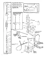
Parts  Drawing ............................................. 16,  17 

Parts List ......................................................... 18 

How to Order  Replacement Parts .......................... 19 

Accessories ..................................................... 19 

Technical  Data ......... , ........................... Back Cover 

Warranty ............................................. Back Cover 

ORACO 

MODEL 226-333 SHOWN 

306-941

Rev.  S 

SUPERSEDES  R 

,----------------- WARNING------------------. 

Hazard of  Using  Fluids  Containing  Halogenated  Hydrocarbons 

Never use 1, 1, 1-trichloroethane,  methylene chloride, other halogenated hydrocarbon solvents or fluids containing 

such solvents in this equipment. Such use could result in a serious chemical reaction, with the possibility of explo­

sion,  which could cause death,  serious bodily injury and/or substantial property damage. 
Consult your fluid suppliers to ensure that the fluids being used are compatible with aluminum and zinc parts. 

GRACO INC. P.O.  BOX 1441  MINNEAPOLIS,  MN 55440-1444 

Summary of Contents for EH 333 HYDRA-SPRAY 226-333

Page 1: ... Servicing Pump 13 Assembling Pump 13 Replacing the Electric Motor 14 Replacing the Hydraulic Pump 14 Electric Motor Wiring Diagram 15 Parts Drawing 16 17 Parts List 18 How to Order Replacement Parts 19 Accessories 19 Technical Data Back Cover Warranty Back Cover ORACO MODEL 226 333 SHOWN 306 941 Rev S SUPERSEDES R WARNING Hazard of Using Fluids Containing Halogenated Hydrocarbons Never use 1 1 1 ...

Page 2: ...pray and reduces the risk of fluid injection when the tip is not installed Check diffuser operation regularly Follow the Pressure Relief Procedure below then remove the spray tip Aim the gun into a metal pail holding the gun firmly to the pail Using the lowest possible pressure trigger the gun If the fluid emitted is not diffused in to an irregular stream replace the diffuser immediately Tip Guard...

Page 3: ...lso read FIRE OR EXPLOSION HAZARD FIRE OR EXPLOSION HAZARD Static electricity is created by the flow of fluid through the pump and hose If every part of the spray equipment is not properly grounded sparking may occur and the system may become hazardous Sparking may also occur when plugging in or unplugging a power supply cord Sparks can ignite fumes from solvents and the fluid being sprayed dust p...

Page 4: ...age n est pas en place Verifier le fonctionnement du diffuseur regulierement Pour cette verification detendre la pression en observant la Marche a Suivre pour Detendre la Pression donnee plus loin puis enlever l ajutage du pulverisateur Pointer le pistolet dans un seau en metal en le maintenant fermement centre le seau Puis en utilisant la pression la plus faible possible ap puyer sur la gachette ...

Page 5: ...ait la pulverisation Ne pas brancher au debrancher un cordon d alimentation quel qu il soit dans la zone au se fait la pulverisation quand ii y a le moindre risque que des vapeurs encore presentes dans l air prennent feu Mise a la terre ou a la masse Pour reduire les risques de production d etincelles d electricite statique le pulverisateur et tous les equipements utilises au se trouvant dans la z...

Page 6: ...tola Difusor El difusor de la pistola dispersa el chorro pulverizado y reduce el riesgo de inyecci6n cuando no esta instalada la boquilla Revisar con regularidad el funcionamiento del difusor Seguir el procedimiento de descarga de presi6n dado mas abajo y despues sacar la boquilla Apuntar la pistola a un balde metalico sosteniendola bien firme contra el Utilizando la presi6n mas bajo posible dispa...

Page 7: ...n la puesta a tierra en malas condiciones Leer tambien la infor maci6n sobre RIESGO DE INCENDIO O EXPLOSION mas arriba PELIGRO DE INCEND O 0 EXPLOSION El flujo a alta velocidad del fluido al pasar por la bomba y manguera crea electricidad estatica Si todas las partes del equipo pulverizador no tienen buena tierra pueden ocurrir chispas convirtiendo al sistema en algo peligroso Tambien pueden produ...

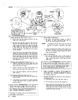
Page 8: ...talled The shield encloses the fan and other moving parts which can cause serious bodily in jury including amputation The shield also con tains important WARNING information Operating the sprayer without the shield in place may cause it to overheat 8 306 941 4 Check Electrical Service a Be sure the electrical service is 120 V 60 HzAC 15 Amp minimum and that the outlet you use is properly grounded ...

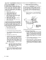
Page 9: ...shing and static spark ing which can cause fire or explosion With the 5 Storage Water base paint flush with water then mineral spirits and leave the pump hose and gun filled with mineral spirits Shutoff and unplug the sprayer open the drain valve to relieve pressure and leave open Oil base paint flush with mineral spirits Shutoff and unplug the sprayer open the drain valve to relieve pressure and ...

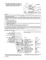
Page 10: ...n the ON OFF switch to ON and slowly increase the pressure setting until the sprayer starts Keep the gun triggered until all air is forced out of the system and the paint flows freely from the gun Release the trigger and engage the safety NOTE If the pump is hard to prime place a con tainer under the drain valve and open it When fluid comes from the valve close it Then disengage the gun safety and...

Page 11: ...eck the wet cup every eight hours to prevent overflow 2 Clean the fluid filter often and whenever the sprayer is stored First follow the Pressure Relief Procedure Warning on page 10 Refer to manual 307 273 supplied for the cleaning procedure 3 Flush the sprayer at the end of each work day and fill it with mineral spirits to help prevent pump corrosion and freezing See Flushing Guidelines on page 9...

Page 12: ...tric motor stops while spraying Electric motor runs but paint pump won t work Paint pump runs but output low on up stroke down stroke both strokes Excessive leakage around hydraulic CAUSE motor piston rod wiper Paint leaks into wet cup Excessive surge at spray gun Not enough paint breakup Paint coating too thick Tails or fingers in spray pattern Spitting from spray gun Static sparking from spray g...

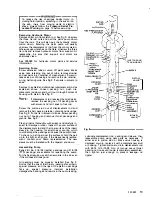
Page 13: ...all packing retainer glands and packings See Fig 9 Put parts in solvent to soak Screw packing nut out of housing and remove throat packings and glands See Fig 9 Clean all parts thoroughly with solvent and carefully in spect for damage or wear Inspect the outer surface of the displacement rod and the inner surface of the insert sleeve in the housing for scratches or scoring which could damage the p...

Page 14: ...ll parts on new motor When reassembl ing nipple be sure to engage threads at least five full turns Carefully put the new motor through coils force it into support mounting and screw the mounting bolts in tightly See Fig 11 Set the gap between the two coupling halves at 0 31 in 0 8 mm then tighten setscrew firmly See Fig 11 Clean sump of sediment and reassemble unit using a new sump gasket Pour hyd...

Page 15: ...ring Diagram NOTE The sprayer is wired for 115 volt service A licensed electrician can rewire it for 230 volt service if necessary FROM MOTOR FOR 115V SERVICE FROM MOTOR 4 J IN_SULATE 9 FOR230V SERVICE Fig 13 306 941 15 ...

Page 16: ...135 tJ Displacement Pump Repair Kit Must be ordered separately Ref No _ 2 5 gal 19 liter Suction Tube Assy 218 136 with leather packings Consists of Ref No Oty 12 1 13 1 14 1 15 3 16 1 19 1 20 1 21 3 22 1 23 1 24 1 26 1 66 1 218 136 with PTFE packings Consists of Ref No Oty 12 1 13 1 14 1 16 1 20 1 22 1 23 4 __ 24 _ 4 Torque to 55 75 ft lb 75 96 N r11J 147 1 Torque into hydraulic motor 15 25 ft lb...

Page 17: ...Ref No 33 Shield Assy Includes items 34 40 39 44 80 Sugge ted Replacement Parts 306 941 17 ...

Page 18: ...ring PTFE RETAINER a ring SLEEVE housing GUIDE ball FRAME cart HANDLE cart SUPPORT motor pump SHIELD sprayer includes items 34 40 RIVET blind 1 8 dia CLIP spring tension PLUG LABEL instruction LABEL instruction 1 113 210 659 BALL VALVE see 306 861 for parts 1 39 176 375 LABEL warning 1 114 167 907 KNOB valve adjustment 1 40 176 115 SHIELD bare 1 116 214 911 PANEL enclosure air 1 44 208 914 GUARD f...

Page 19: ...used where one tip does not provide sufficiently ti wide spray pattern or work piece demands two spray patterns angled in opposite directions STATIC FREE FLUID HOSE Nylon 3000psi 210 bar MAXIMUM WORKING PRESSURE Part No ID Length Thd Size 214 701 3 16 4 8 mm 3 ft 914 mm 1 4 npt mxf 210 540 1 4 6 4 mm 26 ft 7 6 ml 1 4 npsm f 210 541 1 4 6 4 mm 50 ft 15 2 m 1 4 npsm f 214 703 3 8 9 5 mm 25 ft 7 6 m ...

Page 20: ... and Graco shall not be liable for any malfunction damage or wear caused by faulty installation misapplication abrasion corrosion inadequate or improper maintenance negligence accident tampering or substitution of non Graco component parts Nor shall Graco be liable for malfunction damage or wear caused by the incompatibility with Graco equipment of structures accessories equip ment or materials no...

Reviews: