


308-088
To reduce the risk of serious bodily injury, including
fluid injection; splashing in the eyes; injury from
moving parts or electric shock, always follow the
%&&'% "! %$'% %#!#
on page 11
before continuing.
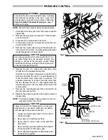
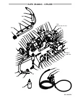
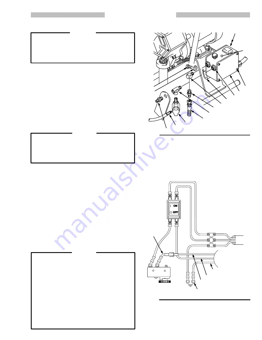
Refer to Fig 20 except where noted otherwise.
1 Disconnect the hose (26) from the pressure control
nipple (30).
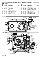
2 Remove the screws (3) and cover (17) from the presĆ
sure control (18).
3 Disconnect the motor leads.
4 At the pressure control, unscrew the nut on the conĆ
duit connector (305).
5 Remove the screws (68) and pull the pressure conĆ
trol away from the frame, carefully guiding the motor
leads through the connector (305).
Use extreme caution when removing the tee (11) or
any other fitting from the pressure control. Any
twisting or jarring of the pressure control fitting
could alter the factory setting of the control or perĆ
manently damage the control.
6 Remove the tee (11), nipple (30) and drain valve
(35,36) from the old pressure control.
Hold the nut (A) firmly at the pressure control with a
wrench and rotate the tee 90
counterclockwise to
move the drain valve away from the sprayer. This
provides clearance to remove the drain valve from
the tee. Remove the tee (11) and nipple assembly.
Install these parts in the new pressure control in the
reverse order.
7 Remove the mounting bracket (52) and install it on
the new pressure control.
8 Replace the pressure control in the reverse order of
disassembly.
The harness adapter (13g) is used only with a reĆ
placement motor.
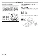
Failure to observe the following may cause poor
performance or excessive pressure and permaĆ
nent damage to the pressure control:
1. Always use nylon spray hose at 15.2 m (50 ft)
minimum length.
2. Never use a wire braid spray hose.
3. Never attach a spray hose to the pressure
drain valve.
4. Never add any type of shutoff device between
the pump outlet and the spray gun.
5. Never allow flushing water or water base paint
to freeze in the system.
69
30
11
26
35
36
30
68
39
305
!
3
17
18
52
MICROSWITCH
ON/OFF
SWITCH
POWER
CORD
BROWN
BLUE
GRN/YEL
MOTOR LEADS
ATTACH TO
GROUNDING SCREW (302)
!
13g
Summary of Contents for EM 390
Page 4: ... 0 0 2 6635 9 1 0 7 4 2 322 7 7 36 2 82 0 0 0 0 0 0 0 0 0 0 2 1 0 0 0 0 ...
Page 14: ... 0 0 0 ...
Page 16: ... ...
Page 20: ... ...
Page 23: ... ...
Page 25: ... ...
Page 26: ... 0 1 0 0 0 1 6 2 0 3 0 7 7 7 2 3 1 021 1 4 5 2 1 0 6 0 ...
Page 27: ... ...


