Models
4
313872B
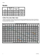
Models
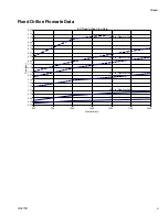
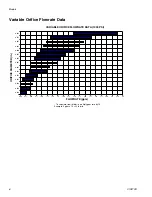
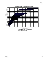
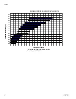
Orifice Flow Area Ratio Chart
In general, flow area ratio should be equal to material ratio but will be influenced by material viscosity. The ideal flow
area ratio is dependent on flow rates, material viscosity, and material ratio. Choose the correct size orifices to equal-
ize fluid pressures at the proportioner.
Part
Purge Rod
Diameter
in. (mm)
Orifice Size
in. (mm)
Handle Type
257999
0.250 (6.35)
0.031 (0.79)
Handheld
24C932
0.250 (6.35)
0.031 (0.79)
Auto
24C933
0.375 (9.53)
0.047 (1.2)
Handheld
24C934
0.375 (9.53)
0.047 (1.2)
Auto
Available Orifice Flow Area Ratios
Dia-
meter 0.016 0.020 0.024 0.028 0.031 0.035 0.039 0.042 0.047 0.052 0.055 0.060 0.063 0.067 0.073 0.086
Flowrate
Increases
as
Diameter
Increases=>
0.016
1.0
1.6
2.3
3.1
3.8
4.8
5.9
6.9
8.6
10.6
11.8
14.1
15.5
17.5
20.8
28.9
0.020
1.6
1.0
1.4
2.0
2.4
3.1
3.8
4.4
5.5
6.8
7.6
9.0
9.9
11.2
13.3
18.5
0.024
2.3
1.4
1.0
1.4
1.7
2.1
2.6
3.1
3.8
4.7
5.3
6.3
6.9
7.8
9.3
12.8
0.028
3.1
2.0
1.4
1.0
1.2
1.6
1.9
2.3
2.8
3.4
3.9
4.6
5.1
5.7
6.8
9.4
0.031
3.8
2.4
1.7
1.2
1.0
1.3
1.6
1.8
2.3
2.8
3.1
3.7
4.1
4.7
5.5
7.7
0.035
4.8
3.1
2.1
1.6
1.3
1.0
1.2
1.4
1.8
2.2
2.5
2.9
3.2
3.7
4.4
6.0
0.039
5.9
3.8
2.6
1.9
1.6
1.2
1.0
1.2
1.5
1.8
2.0
2.4
2.6
3.0
3.5
4.9
0.042
6.9
4.4
3.1
2.3
1.8
1.4
1.2
1.0
1.3
1.5
1.7
2.0
2.3
2.5
3.0
4.2
0.047
8.6
5.5
3.8
2.8
2.3
1.8
1.5
1.3
1.0
1.2
1.4
1.6
1.8
2.0
2.4
3.3
0.052
10.6
6.8
4.7
3.4
2.8
2.2
1.8
1.5
1.2
1.0
1.1
1.3
1.5
1.7
2.0
2.7
0.055
11.8
7.6
5.3
3.9
3.1
2.5
2.0
1.7
1.4
1.1
1.0
1.2
1.3
1.5
1.8
2.4
0.060
14.1
9.0
6.3
4.6
3.7
2.9
2.4
2.0
1.6
1.3
1.2
1.0
1.1
1.2
1.5
2.1
0.063
15.5
9.9
6.9
5.1
4.1
3.2
2.6
2.3
1.8
1.5
1.3
1.1
1.0
1.1
1.3
1.9
0.067
17.5
11.2
7.8
5.7
4.7
3.7
3.0
2.5
2.0
1.7
1.5
1.2
1.1
1.0
1.2
1.6
0.073
20.8
13.3
9.3
6.8
5.5
4.4
3.5
3.0
2.4
2.0
1.8
1.5
1.3
1.2
1.0
1.4
0.086
28.9
18.5
12.8
9.4
7.7
6.0
4.9
4.2
3.3
2.7
2.4
2.1
1.9
1.6
1.4
1.0
Flowrate Increases as Diameter Increases =>


