


Kits
313872B
45
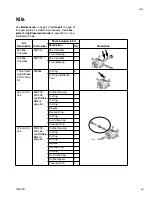
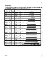
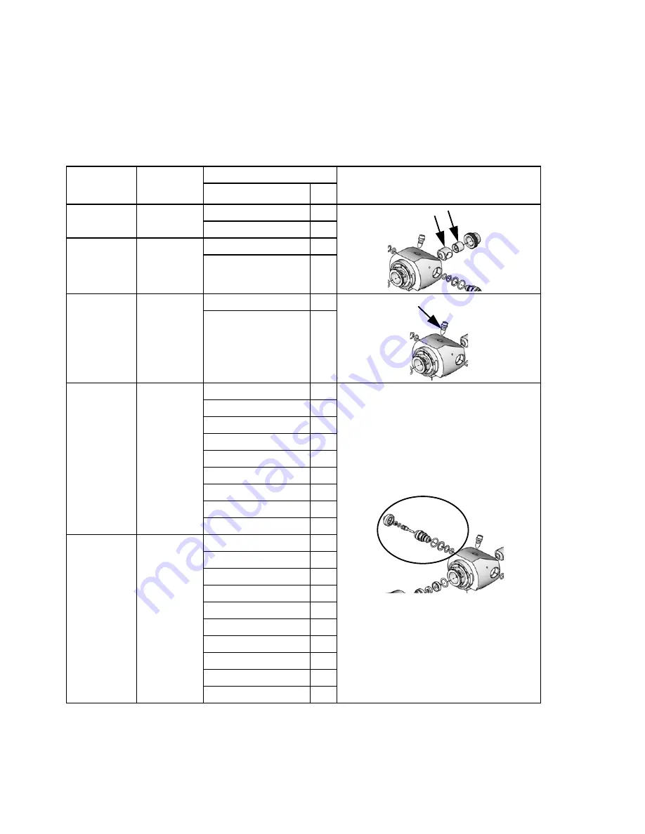
Kits
See
Maintenance
on page 24 and
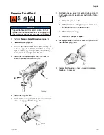
Repair
on page 31
for appropriate kit installation procedures. See
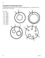
Com-
plete O-ring Placement Guide
on page 52 for o-ring
identification help.
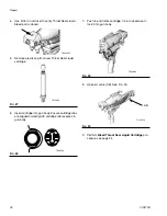
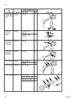
Kit
Description
Kit Number
Parts included in Kit
Illustration
Description
Qty
250 Mix
Chamber
24D314
Mix Chamber
1
Front Bearing
1
375 Mix
Chamber
24D322
Mix Chamber
1
Front Bearing
1
Throat Seal
Liquid Bleed
Port O-Ring
Kit
246354
O-Ring
6
O-Ring Installation
Tool
1
250 Iso Ori-
fice
24D223 -
24D238;
see
Orifice
Kits
on
page 50
Orifice Housing
1
O-Ring
1
O-Ring
1
O-Ring
1
Needle
1
Backup Ring
1
O-Ring
1
Iso Orifice Cap
1
Cleanout Drill
1
375 Iso Ori-
fice
24D239 -
24D254;
see
Orifice
Kits
on
page 50
Orifice Housing
1
O-Ring
1
O-Ring
1
O-Ring
1
Needle
1
Backup Ring
1
O-Ring
1
Iso Orifice Cap
1
Orifice Spacer
1
Cleanout Drill
1


