Warnings
3A5053B
3
Warnings
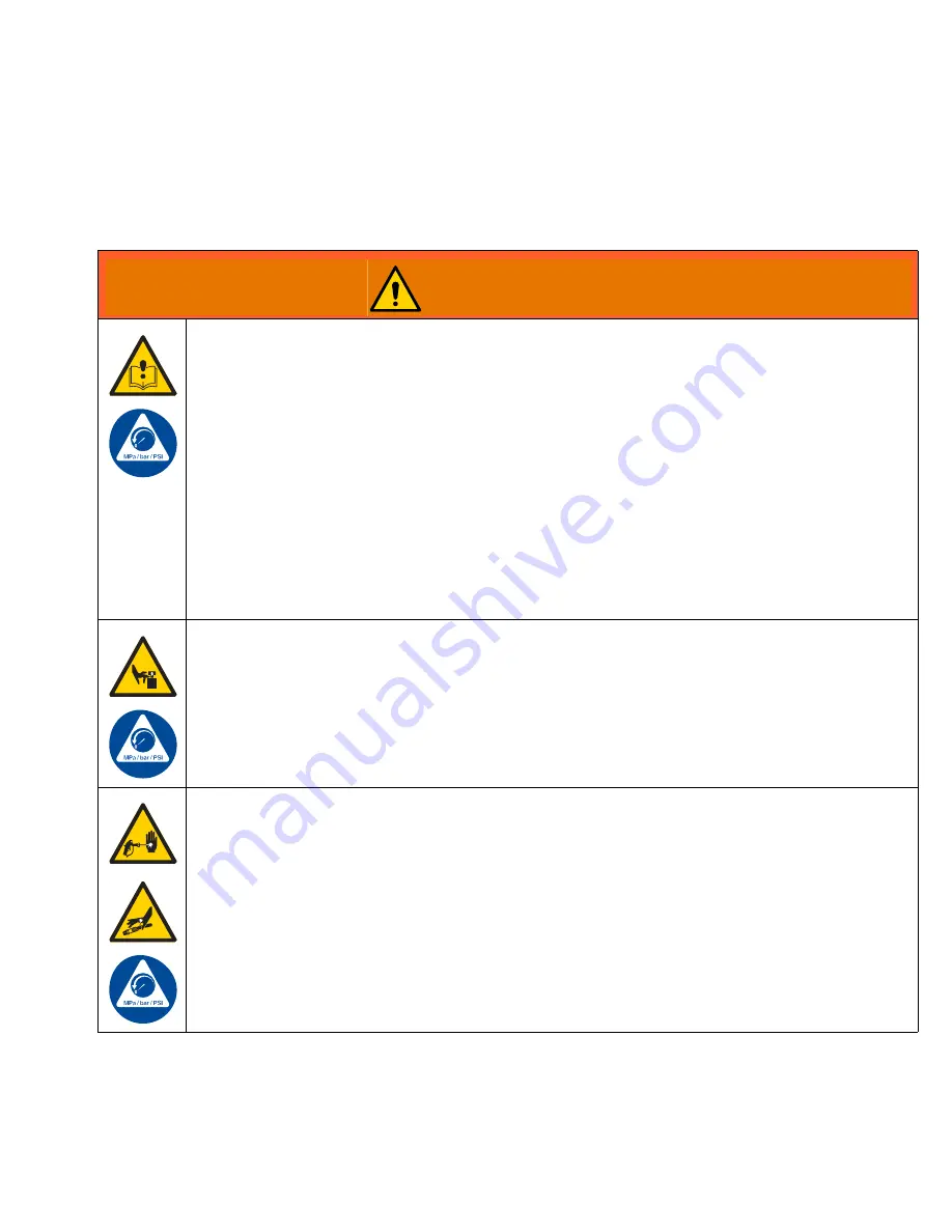
The following warnings are for the setup, use, grounding, maintenance, and repair of this equipment. The exclamation
point symbol alerts you to a general warning and the hazard symbols refer to procedure-specific risks. When these
symbols appear in the body of this manual or on warning labels, refer back to these Warnings. Product-specific hazard
symbols and warnings not covered in this section may appear throughout the body of this manual where applicable.
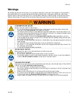
WARNING
EQUIPMENT MISUSE HAZARD
Misuse can cause death or serious injury.
•
Do not exceed the maximum working pressure or temperature rating of the lowest rated system
component. See
Technical Data
in all equipment manuals.
•
Use fluids and solvents that are compatible with equipment wetted parts. See Technical Data in all
equipment manuals. Read fluid and solvent manufacturer’s warnings. For complete information about
your material, request MSDS from distributor or retailer.
•
Turn off all equipment and follow the
Pressure Relief Procedure
when equipment is not in use.
•
Check equipment daily. Repair or replace worn or damaged parts immediately with genuine manufac-
turer’s replacement parts only.
•
Do not alter or modify equipment. Alterations or modifications may void agency approvals and create
safety hazards.
•
Use equipment only for its intended purpose. Call your distributor for information.
•
Do not use 1,1,1-trichloroethane, methylene chloride, other halogenated hydrocarbon solvents or flu-
ids containing such solvents.
•
Comply with all applicable safety regulations.
MOVING PARTS HAZARD
Moving parts can pinch, cut or amputate fingers and other body parts.
•
Keep clear of moving parts.
•
Do not operate equipment with protective guards or covers removed.
•
Pressurized equipment can start without warning. Before checking, moving, or servicing equipment,
follow the
Pressure Relief Procedure
and disconnect all power sources.
SKIN INJECTION HAZARD
High-pressure spray is able to inject toxins into the body and cause serious bodily injury. In the event that
injection occurs,
get immediate surgical treatment.
•
Do not aim the gun at, or spray any person or animal.
•
Keep hands and other body parts away from the discharge. For example, do not try to stop leaks with
any part of the body.
•
Always use the nozzle tip guard. Do not spray without nozzle tip guard in place.
•
Do not leave the unit energized or under pressure while unattended. When the unit is not in use, turn
off the unit and follow the
Pressure Relief Procedure
for turning off the unit.
•
Always engage the trigger lock when not spraying. Verify the trigger lock is functioning properly.


