background image

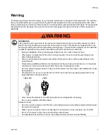
警告


8

333119D

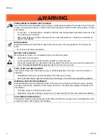
WARNING

WARNING

WARNING

WARNING

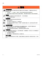
警告

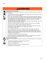
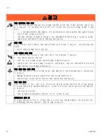
火灾和爆炸危险
工作区内的溶剂和油漆味等可燃烟气会引发火灾或爆炸危险。 为避免火灾及爆炸:

不要在明火或诸如烟头、电机及电气设备等火源附近喷涂易燃或可燃材料。

本喷涂机内流经的涂料或溶剂可产生静电。 存在溶剂或涂料烟雾的情况下,静电有引发火灾或爆炸的
危险。 喷涂系统的所有零配件,其中包括泵、软管组件、喷枪和喷涂区内和周围的物体均应妥善接
地,以防止静电放电和火花。 应使用 Graco 导电或接地的高压无气油漆喷涂机软管。

检查确认所有容器及收集系统均已接地,以防止出现静电放电。 请勿使用桶衬垫,除非它们防静电或
导电。

连接到接地插座并使用接地的加长电线。 不要使用 3-2 转换适配器。

不要使用含有卤代烃的涂料或溶剂。

使喷涂区域保持良好的通风。 使喷涂区有大量的新鲜空气流通。 将泵组件放在通风良好的地方。 
不要喷涂泵组件。

不要在喷涂区域吸烟。

不要在喷涂区域操作电灯开关、发动机或其它可产生电火花的产品。

保持该区域清洁,无涂料或溶剂容器、碎片及其它可燃材料。

了解所喷涂的涂料和溶剂的成分。 阅读涂料和溶剂随附的所有材料安全数据表 (MSDS) 和容器标签。 
遵守涂料和溶剂制造商的安全说明。

应配有工作性能良好的灭火设备。

喷涂机会产生电火花。 当喷涂机使用易燃液体或在其附近使用易燃液体或用易燃液体进行冲洗或清洗
时,要让喷涂机离开爆炸性蒸气至少 20 英尺 (6 m)。

触电危险
系统接地不当、设置不正确或使用不当都可导致电击。

进行设备维修之前,要关闭电源并切断电源线的连接。

只能连接至已接地的电源插座。

只能使用三芯加长电线。

确保电源及加长电线上的接地插脚完好无损。

不能淋雨。 存放在室内。

Summary of Contents for FinishPro II 295

Page 1: ...r hazardous locations 2800 psi 193 bar 19 3 MPa Maximum Working Pressure Airless Spraying 2800 psi 193 bar 19 3 MPa 2800 psi 193 bar 19 3 MPa Models Important Safety Instructions Read all warnings and...

Page 2: ...28 Clearing a Clogged Tip 29 Cleanup 30 Repair 34 Compressor Motor Replacement 34 Basic Troubleshooting 38 General Problem No Output 42 General Problem Excessive Pressure Build Up 42 43 47 47 47 48 53...

Page 3: ...lectric shock When repair or replacement of the cord or plug is required do not connect the grounding wire to either flat blade terminal The wire with insulation having an outer surface that is green...

Page 4: ...paint or a solvent containing halogenated hydrocarbons Keep spray area well ventilated Keep a good supply of fresh air moving through the area Keep pump assembly in a well ventilated area Do not spra...

Page 5: ...gger lock when not spraying Verify the trigger lock is functioning properly Verify that all connections are secure before operating the unit Know how to stop the unit and bleed pressure quickly Be tho...

Page 6: ...ized equipment can start without warning Before checking moving or servicing equipment follow the Pressure Relief Procedure and disconnect all power sources TOXIC FLUID OR FUMES HAZARD Toxic fluids or...

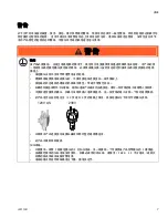
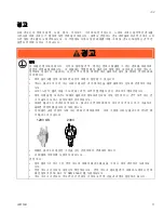
Page 7: ...333119D 7 WARNING WARNING WARNING WARNING 120 230 3 3 3 12 AWG 2 5 120V US 230V...

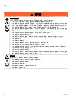
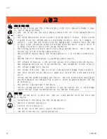
Page 8: ...8 333119D WARNING WARNING WARNING WARNING Graco 3 2 MSDS 20 6 m...

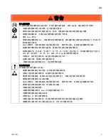
Page 9: ...333119D 9 Graco 3300 227 22 7 3300 227 22 7 Graco Graco 25 WARNING WARNING WARNING WARNING...

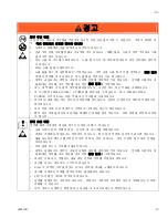
Page 10: ...10 333119D 1 1 1 MSDS 65 WARNING WARNING WARNING WARNING...

Page 11: ...333119D 11 WARNING WARNING WARNING WARNING 120V 230V 3 12 AWG 2 5mm2 120V US 230V...

Page 12: ...12 333119D WARNING WARNING WARNING WARNING Graco 3 2 MSDS 20ft 6m 3...

Page 13: ...333119D 13 Graco 3300psi 227bar 22 7MPa 3300psi 227bar 22 7MPa Graco Graco 25ft WARNING WARNING WARNING WARNING...

Page 14: ...14 333119D 1 1 1 MSDS 65 WARNING WARNING WARNING WARNING...

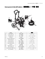
Page 15: ...A Drain Tube Hose B Air Hose Connection C Prime Spray Valve D Fluid Outlet E Air and Fluid Supply Hoses F Displacement Pump G Gun see manual H Fluid Pressure Control J Power Function Selector K Gun F...

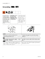
Page 16: ...oper grounding can cause electric shock Grounding provides an escape wire for the electric current English The sprayer cord includes a grounding wire with an appropriate grounding contact Do not use i...

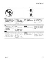
Page 17: ...0 Hz 15A 1 phase 230V units require 230 VAC 50 60 Hz 10A 1 phase Extension Cords Use an extension cord with an undamaged ground contact If an extension cord is neces sary use a 3 wire 12 AWG 2 5 mm2 m...

Page 18: ...ve surface such as paper or cardboard which interrupts grounding continuity Grounding a metal pail con nect a ground wire to pail by clamping one end to pail and other end to a true earth ground such...

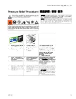
Page 19: ...cing the equipment 1 Set power function selection switch to OFF and unplug sprayer 2 Turn pressure control knob to lowest setting 3 Hold gun to side of grounded metal pail Trigger the gun to relieve p...

Page 20: ...h Connect hoses to sprayer 1 Attach fluid supply hose to fluid fitting Tighten securely 2 Attach air supply hose to sprayer air fitting Connect Gun to hoses 1 Lay connected hoses flat and next to each...

Page 21: ...securely 5 Cut air hose to length and couple to air connection on gun 6 Connect air hose to barb on air gun 7 If air cap is installed on gun remove it 8 Remove and check inlet strainer for clogs and...

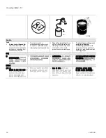
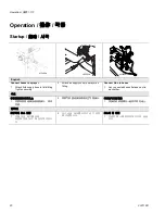
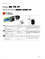
Page 22: ...ly grounded electrical outlet 3 Engage trigger lock 4 Turn prime valve to PRIME 5 Place suction tube in grounded metal pail partially filled with flushing fluid and drain tube in waste pail Attach gro...

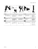
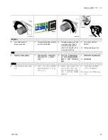
Page 23: ...AIRLESS 8 Increase pressure to start motor and allow fluid to circulate through drain tube for 15 seconds then turn pressure down 9 Turn prime valve to SPRAY 10 Disengage trigger lock 6 7 AIRLESS 8 15...

Page 24: ...e Relief proce dure Tighten fittings Repeat steps 1 9 of Startup page 22 If no leaks proceed to step 10 12 Place siphon tube in paint pail 13 Trigger gun again into flushing pail until paint appears M...

Page 25: ...33b over seat 33a Use black seal for water based materials and orange for solvent and oil based materials 5 Insert tip 33 into slot A in air cap 6 Notice If air cap is not fully installed on gun flui...

Page 26: ...install an in line desiccant filter 24U981 or 24U982 to elimi nate moisture going into gun 1 Turn air adjustment valve off at gun 2 Increase fluid pressure to eliminate tails 3 Decrease fluid pressure...

Page 27: ...unction selection switch to AA Air Assisted or ON 5 Trigger gun and turn gun air adjustment valve until tails disappear and good spray pattern is achieved 6 AA ON 7 6 AA Air Assisted ON 7 AIRLESS OFF...

Page 28: ...e fluid pressure until you achieve a consistent spray pattern without heavy edges Use a smaller tip size if pressure adjustment alone does not eliminate heavy edges Hold gun perpendicular and 10 12 in...

Page 29: ...clean guard and tip RAC Tip proceed to step 3 3 Rotate tip 180 4 Disengage trigger lock 5 Trigger gun into pail or onto ground to remove clog 6 Engage trigger lock 7 Rotate tip back 180 to spray posit...

Page 30: ...setting Trigger gun to relieve pressure 3 Engage trigger lock 4 Put drain tube in pail 5 Turn prime valve to PRIME 6 Remove tip and air cap from gun Refer to your gun manual for complete cleaning inst...

Page 31: ...0 Turn prime valve to SPRAY 11 Hold gun against paint pail 12 Disengage trigger lock 13 Trigger gun and increase pressure until flushing fluid appears 14 Stop triggering gun Move gun to flushing pail...

Page 32: ...to drain fluid 16 Turn prime valve to SPRAY 17 Disengage trigger lock and trigger gun into flushing pail to purge fluid from hose 18 Set function selection switch to AA Air Assisted or ON 19 Trigger g...

Page 33: ...nstall filter 24 Wipe sprayer hose and gun with a rag soaked in water or mineral spirits 25 If flushing with water flush again with mineral spirits or Pump Armor to leave a protective coating to preve...

Page 34: ...ish Compressor Belt Removal 1 Remove three screws and belt cover 2 Remove three screws and belt guide plate 3 Loosen top and bottom idler pulley bracket screws 4 Pull idler back and remove belt from p...

Page 35: ...ews 2 Place torque wrench in square hole and torque to 60 in lb to properly tension belt Tighten top and bottom idler screws 3 Torque top and bottom idler screws to 120 in lb 4 Install belt cover with...

Page 36: ...down and forward to remove from sprayer Place compressor on workbench 4 Perform belt removal procedure page 34 5 Remove two screws and IEC cord clamp Remove two screws and compressor shroud 6 Disconne...

Page 37: ...ressor shroud with two screws Install IEC cord clamp with two screws 4 Install air inlet fitting and perform Belt Installation page 35 5 Tip compressor assembly up and back into frame Install four scr...

Page 38: ...may be clogged Relieve Pressure page 19 Then clear clog or clean gun filter Refer to gun instruction manual 313347 Basic Mechanical 1 Pump frozen or hardened paint Thaw sprayer if water or water based...

Page 39: ...ads are securely fastened and properly connected to control board Replace loose terminals crimp to leads Be sure terminals are firmly connected Clean circuit board terminals Securely reconnect leads 6...

Page 40: ...nsulation and terminals for signs of overheating Be sure male terminal pins are centered and firmly connected to female terminals Replace any loose terminals or damaged wiring Securely reconnect termi...

Page 41: ...open 2 Air connections may be loose Check all connections for leaking air Low air output at gun 3 Damaged leaking air supply hose Replace air supply hose 4 Air intake filter clogged Clean or replace...

Page 42: ...shorted control board Clean out and or dry out and retry Replace if necessary using Pressure Control Switch Kit page 62 Problem Cause Solution Prime Spray valve actuates automati cally relieving press...

Page 43: ...333119D 43 Graco 1 2 19 313347 1 62 2 62 36 1 ON 2...

Page 44: ...44 333119D 65 1 110 120 Vac 105 130 Vac 230 Vac 210 255 Vac 2 3 62 4 ON OFF 65 5 6 62 7 1 4 6mm 62 8 62 9 56 62 10...

Page 45: ...333119D 45 1 19 313347 2 60 3 19 62 4 O 5 110 120 Vac 105 130 Vac 240 Vac 210 255 Vac 6 16 7 8 1 4 6mm 36 9 10 62 11 56 36 12 22 13 15 3 4...

Page 46: ...46 333119D 1 62 2 3 4 O 5 60 6 62 7 62 8 62 1 115 F 46 C 2 36 1 2 3 4 1 ON 2 110 120 Vac 105 Vac 240 Vac 210 Vac 3 4 5 6 65 7 115 F 46 C 8 65 1 2 3 19 313347 1 257824...

Page 47: ...333119D 47 38 62 62 62 62 57 62...

Page 48: ...48 333119D Graco 1 2 19 313347 1 62 2 62 36 1 ON 2 ON OFF...

Page 49: ...333119D 49 65 1 110 120 VAC 105 130 VAC 230 VAC 210 255 VAC 2 3 62 4 ON OFF 65 5 6 62 7 1 4 6mm 62 8 62 9 56 62 10...

Page 50: ...50 333119D 1 19 313347 2 60 3 19 62 4 O 5 110 120 VAC 105 130 VAC 240 VAC 210 255 6 16 7 8 1 4 6 mm 36 9 10 62 11 56 36 12 22 13 15 3 4...

Page 51: ...333119D 51 1 62 2 3 4 O 5 60 6 62 7 62 8 62 1 115 F 46 C 2 36 1 2 3 4...

Page 52: ...52 333119D 1 ON 2 110 120 Vac 105 Vac 240 Vac 210 Vac 3 4 5 0 6 65 7 115 F 46 C 8 65 1 2 3 19 313347 1 257824...

Page 53: ...333119D 53 38 62 62 62 62 57 62...

Page 54: ...gs and brush as follows If Motor Diagnostics reveal a damaged motor or if motor brushes are shorter than 1 4 in 6 4 mm or if the motor shaft cannot turn replace the motor using Motor Kit page 62 Setup...

Page 55: ...D 55 English 3 Remove enclosure and disconnect motor leads from control card 4 Remove fan brace if equipped 5 Remove four screws and front cover 6 Remove yoke and guide rods 7 Remove gear 3 4 5 6 7 3...

Page 56: ...ping If fan does not spin freely armature is shorted Replace motor using Motor Kit page 62 Armature Brushes and Motor Wiring Open Circuit 1 Connect red and black motor leads together with test lead 2...

Page 57: ...TE Check for motor problems before replacing control board A damaged motor may burn out a good control card Check for a damaged con trol board or pressure con trol switch as follows 1 Relieve pressure...

Page 58: ...cover screws and front cover 4 Remove yoke and guide rods 5 Remove gear 6 Remove pressure control harness from control board Use tip of small flat blade screwdriver to press tab on right side connecto...

Page 59: ...installed in pump 8 Turn pressure control adjustment knob clockwise to maximum pressure setting 9 Plug electrical cord into 120Vac receptacle 10 Turn power switch ON If motor runs replace pressure swi...

Page 60: ...to cycle motor and pump run when the spray gun trigger is released or if performance is poor even with new spray tips and clean filters the pump inlet or outlet valve may be obstructed or worn If a p...

Page 61: ...19 23 135d 135c 30 38 31 206 203 221 220 219b 219a 219 215 215 212 215 207a 201 209 207 205 211 214 20a 202a 222 214 214k 214a 214b 214b1 214j 214f 214h 214g 214e 214d 214c 7 213 14 8 25 231 201a 209b...

Page 62: ...CREW mach slot hex wash hd 1 205 122528 SWITCH three position rocker 1 206 15X737 BRACKET switch 1 207 KIT repair board control includes 207a 207b 257802 120V Model 24U060 1 257837 240V Models 24U061...

Page 63: ...Parts List 333119D 63 Parts Compressor ti13423a 106 131 112 142 117 118 120a 120a 120 128 133 136 135 131a 135b 129 138 110 122b 122a 122c 145 135a 122 121 106 144 114 131b ti13423a...

Page 64: ...0V 1 122 257817 KIT repair idler 1 122a 260212 SCREW hex washer hd thd form 2 122b 110755 WASHER plain 1 122c 257818 KIT repair belt 1 128 257342 BASE assemble air filter 1 129 115495 SCREW mach hex w...

Page 65: ...Vac 120 Vac 333119D 65 Wiring Diagram 120 Vac 120 Vac 120 Vac G A B B B C C C C D F E F B B G Fluid Pump Compressor G ti22571a English A Red Wire B Black Wire C White Wire D Blue Wire E Striped Wire...

Page 66: ...0 Vac 240 Vac 66 333119D Wiring Diagram 240 Vac 240 Vac 240 Vac A B D B D A E A A E D A ti13425a Fluid Pump Compressor F G English A Brown Wire B Black Wire D Blue Wire E Grren Yellow Wire F Compresso...

Page 67: ...aximum material pressure AA US UK 3000 psi 207 bar Europe Asia Australia 3000 psi 207 bar Atomizing air output US UK 3000 psi 207 bar Europe Asia Australia 3000 psi 207 bar Air pressure 35 pi 2 4 bar...

Page 68: ...60 10 0 017 0 017 0 017 0 017 47 1 8 54 2 0 0 34 1 28 0 34 1 28 0 34 1 28 AA 3000 207 3000 207 3000 207 3000 207 35 2 4 Hi boy Hi boy 27 68 5 21 53 3 28 71 1 68 31 0 1 2 HP TEFC 7 8 HP 3 16 x 25 1 4 x...

Page 69: ...0 lpm 0 34 gpm 1 28 lpm 0 34 gpm 1 28 lpm 0 34 gpm 1 28 lpm AA 3000 psi 207 bar 3000 psi 207 bar 3000 psi 207 bar 3000 psi 207 bar 35 pi 2 4 bar Hi boy Hi boy 27 in 68 5 cm 21 in 53 3 cm 28 in 71 1 cm...

Page 70: ...o be defective to an authorized Graco distributor for verification of the claimed defect If the claimed defect is verified Graco will repair or replace free of charge any defective parts The equipment...

Reviews: