Motor Replacement
36
333126A
Motor Replacement
FinishPro II 595
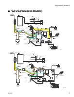
See Wiring Diagram, page 36.
Removal
1. Disconnect power.
2.
Relieve pressure
, page 11.
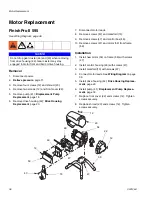
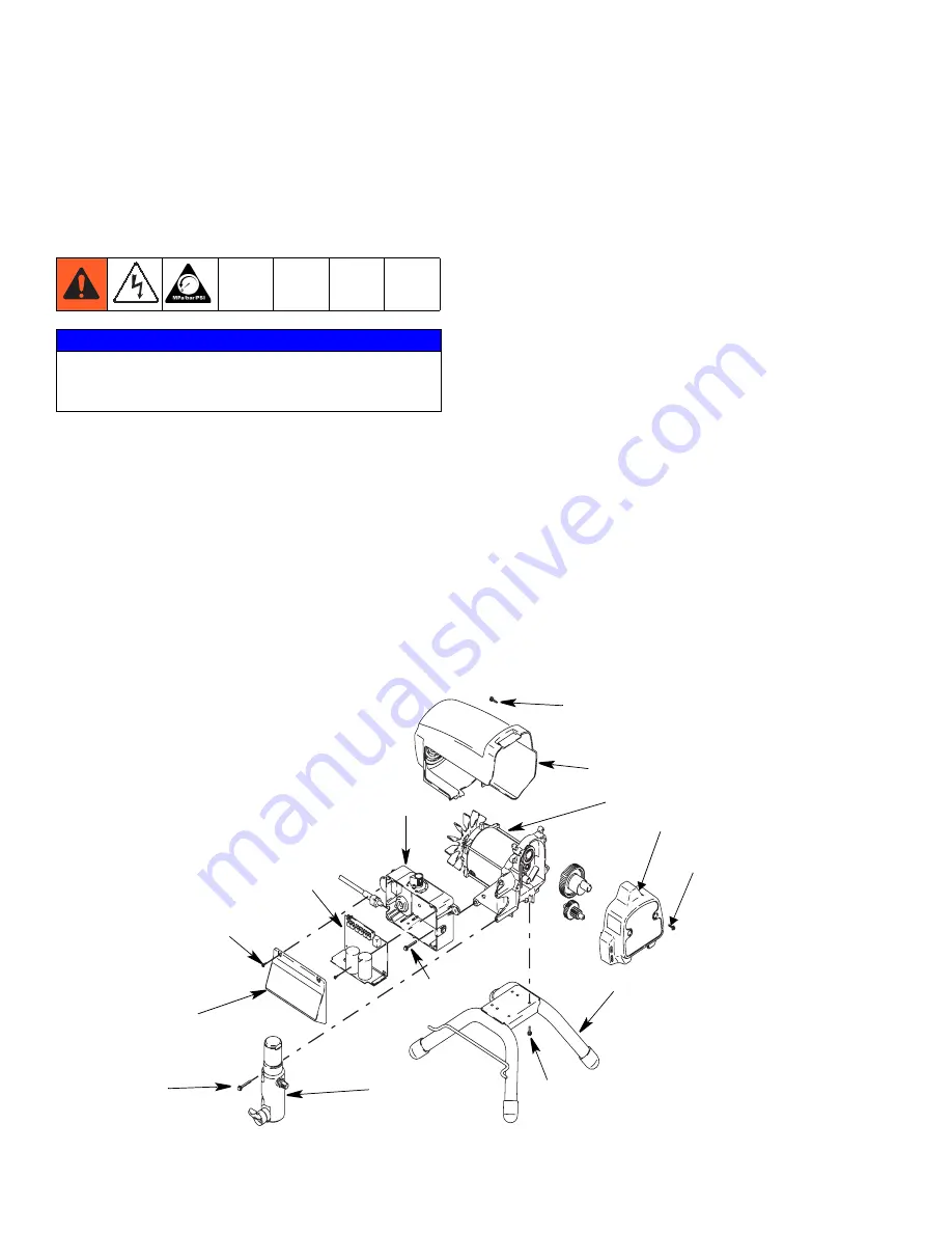
3. Remove four screws (12) and shroud (23).
4. Remove two screws (12) and front cover (22).
5. Remove pump (41);
Displacement Pump
Replacement
, page 18
6. Remove drive housing (42);
Drive Housing
Replacement
, page 20.
7. Disconnect motor leads.
8. Remove screws (47) and manifold (15).
9. Remove screws (47) and control box (48).
10. Remove screws (47) and motor (54) from frame
(59).
Installation
1. Install new motor (54) on frame (59) with screws
(47).
2. Install control housing (48) with screws (47).
3. Install manifold (15) with screws (47).
4. Connect motor leads. See
Wiring Diagram
on page
36.
5. Install drive housing (42);
Drive Housing Replace-
ment
, page 20.
6. Install pump (41);
Displacement Pump Replace-
ment
, page 18.
7. Replace front cover (22) and screws (12). Tighten
screws securely.
8. Replace shroud (23) and screws (12). Tighten
screws securely.
NOTICE
Do not drop gear cluster (44) and (40) when removing
from drive housing (42). Gear cluster may stay
engaged in motor front end bell or drive housing.
ti
74
3
4
a
12
23
12
50
49
48
47
15
47
47
54
59
22
12
Summary of Contents for FinishPro II 395
Page 7: ...Notes 333126A 7 Notes ...
Page 41: ...Notes 333126A 41 Notes ...


