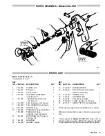
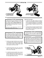
background image

5

307–633

OPERATION

Fig 2

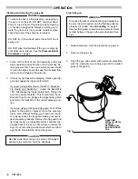
TO ENGAGE THE TRIGGER

SAFETY LATCH (ON SAFE),

 TURN TO RIGHT ANGLE WITH

GUN BODY

TO DISENGAGE TRIGGER

SAFETY LATCH (OFF SAFE),

LIFT AND TURN LATCH

PARALLEL TO GUN BODY

0705

To reduce the risk of serious bodily injury, including
fluid injection or splashing in the eyes or on the
skin, always follow the Pressure Relief Proce-
dure
 on page 2 before checking, servicing, remov-
ing, changing or cleaning spray tips or any part of
the gun or system.

Whenever you stop spraying for a moment, en-
gage the gun safety latch. See Fig 2.

WARNING

WARNING

The wallet-sized warning card provided with this
gun should be kept with the operator at all times.
The card contains important treatment information
should an injection injury occur. Additional cards
are available from Graco Inc. at no charge.

1.

Start the pump. Adjust the fluid pressure so the spray
is completely atomized. Always use the lowest pres-
sure necessary to get the desired results. Higher
pressure may not improve the spray pattern and will
cause premature tip and pump wear.

2.

If adjusting the pressure does not give a good spray
pattern, try another tip size. Relieve pressure com-
pletely before changing tips.

3.

For maximum seat and needle life, Use a full-open,
full-close trigger action. Hold the gun about 14 in.
(350 mm) from and at right angles to the work sur-
face. Don’t swing the gun in an arc. Practice to find
the best length and speed of stroke.

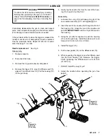
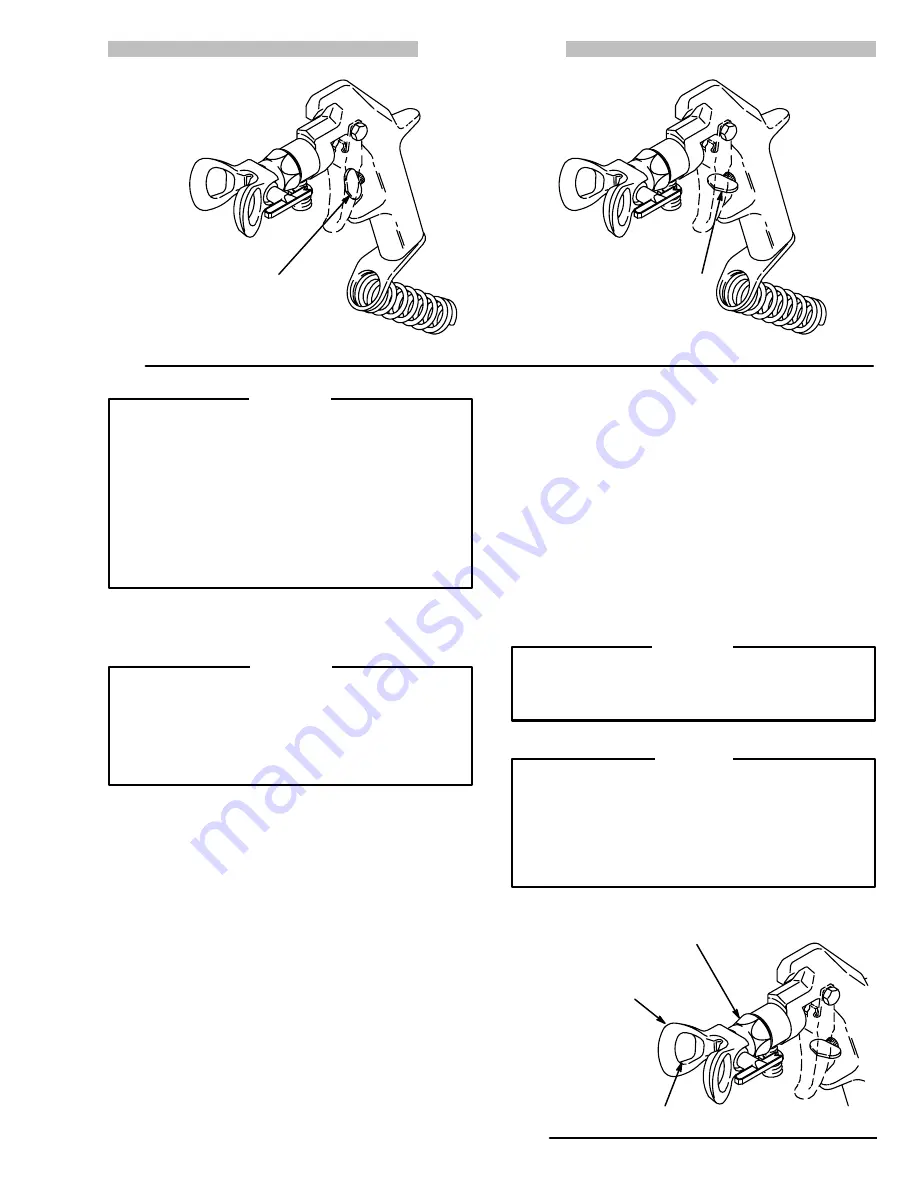
Adjust the spray pattern

1.

To adjust the spray pattern direction, first relieve
pressure. Be sure the trigger safety latch is engaged.
Loosen the tip guard retaining nut. Turn the tip guard
so it is vertical for vertical pattern and horizontal for
a horizontal pattern. Tighten the retaining nut. See
Fig 3.

2.

The spray tip orifice size and spray angle determines
the coverage and size of pattern. When more cover-
age is needed, use a larger spray tip rather than in-
creasing the fluid pressure.

WARNING

To reduce the risk of a fluid injection injury, NEVER
use the gun with the tip guard or trigger safety
removed.

Openings in the tip guard are designed to reduce
paint buildup on the guard when spraying. Any
damage to the sharp edges of the openings causes
paint to collect at that area. To reduce the risk of
damage, never hang the gun by the tip guard. See
Fig 3.

CAUTION

Fig 3

TIP GUARD SHOWN

IN POSITION

FOR HORIZONTAL

PATTERN

RETAINING NUT

DO NOT DAMAGE

THESE EDGES

0706

Summary of Contents for FLEX 218-13

Page 1: ...size SwitchTip Has two finger trigger Model 218 132 Series C Includes standard tip guard and flat tip Has two finger trigger A four finger trigger is available See page 11 TABLE OF CONTENTS Warnings 2...

Page 2: ...e tip is not installed Check the diffuser opera tion regularly Follow the PRESSURE RELIEF PROCEDURE below then remove the spray tip Aim the gun into a metal pail holding the gun firmly to the pail Usi...

Page 3: ...e a tag on it which specifies the maximum electrical resistance con tact the hose supplier or manufacturer for the maximum resis tance limits Use a resistance meter in the appropriate range for your h...

Page 4: ...in the displacement pump hose and gun triggering the gun to relieve pressure may not be sufficient WARNING 1 Guide a grounded fluid hose A through the hose guard 8 and connect the hose to the gun inl...

Page 5: ...spray pattern try another tip size Relieve pressure com pletely before changing tips 3 For maximum seat and needle life Use a full open full close trigger action Hold the gun about 14 in 350 mm from a...

Page 6: ...ste container This should force the ob struction from the tip Engage the trigger safety latch and return the SwitchTip to the normal spraying posi tion If you are using a flat tip and tip guard shut o...

Page 7: ...4 and setscrew 12 Pull the housing 19 off the gun body 5 Gently tap the needle 18 from the rear of the hous ing 19 to push it out the front Reassembly 1 Lubricate the o ring D and backup ring E of the...

Page 8: ...urn the needle clockwise until it does 2 With light pressure hold the trigger against the latch Turn the needle counterclockwise until there is enough tension for you to feel and see the trigger raise...

Page 9: ...GUARD hose 1 10 169 550 TRIGGER 2 finger standard 1 170 668 TRIGGER 4 finger optional order separately 1 12 102 207 SETSCREW soc hd cup pt 1 4 20 x 1 4 1 13 169 797 ADAPTER 1 14 156 766 GASKET copper...

Page 10: ...172 479 TAG instruction not shown 1 7 180 044 TAG WARNING not shown 1 8 218 139 GUARD hose 1 10 169 550 TRIGGER 2 finger standard 1 170 668 TRIGGER 4 finger optional order separately 1 12 102 207 SETS...

Page 11: ...as indicated on pages 8 and 9 4 FINGER TRIGGER KIT 170 668 Replaces standard 2 finger trigger NYLON BRUSHES 101 891 3 8 9 mm dia 101 892 5 8 16 mm dia WRENCH 171 147 Fits all hexes on the gun SERVICE...

Page 12: ...ion of the claim If the claimed defect is verified Graco will re pair or replace free of charge any defective parts The equipment will be returned to the original pur chaser transportation prepaid If...

Reviews: