background image

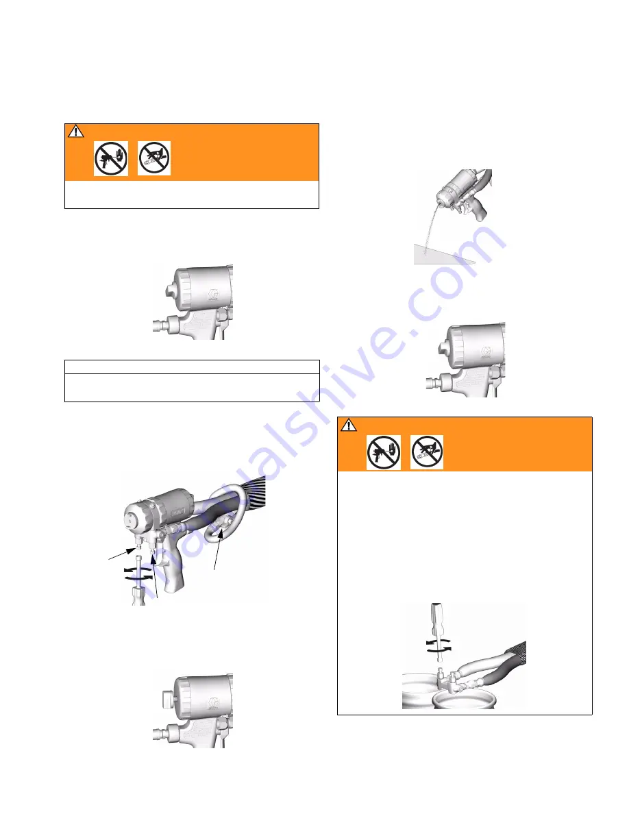
Pressure Relief Procedure

309550U

15

Pressure Relief Procedure

WARNING

Read warnings, page 7. Relieve pressure before 
cleaning or repairing gun.

1.

Engage piston safety lock, page 10.

CAUTION

Air supply is required for gun actuation. Do not dis-
connect gun air supply until fluid pressure is relieved.

2.

Close fluid valves A and B. Leave air valve (W) 

open.

3.

Disengage piston safety lock, page 10.

TI2409A

TI2421A

A

B

W

TI2410A

4.

Trigger gun onto cardboard or into waste container 

to relieve pressure.

5.

Engage piston safety lock, page 10.

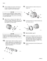
WARNING

Fluid in the hose and proportioner is still under pres-
sure. Follow the Pressure Relief Procedure in the pro-
portioner manual.

To relieve pressure in the hose after the gun is 
removed, place the fluid manifold over containers, fac-
ing away from you. Very carefully open the fluid valves. 
Under high pressure, fluid will spray sideways from the 
fluid ports.

TI4722a

TI2409A

TI2484A

Summary of Contents for Fusion 246099

Page 1: ...mmable foam and polyurea Not for use in explosive atmospheres 3500 psi 24 5 MPa 245 bar Maximum Fluid Working Pressure 80 130 psi 0 56 0 9 MPa 5 6 9 0 bar Air Inlet Pressure Range 200 F 94 C Maximum Fluid Temperature US Patent Number D479 305 Korean Patent 338185 Australian Patent Number 152610 Important Safety Instructions Read all warnings and instructions in this manual Save these instructions ...

Page 2: ...ifold 20 Clean Mix Chamber Nozzle 21 Clean Passages 21 Clean Impingement Ports 21 Troubleshooting 23 Repair 27 Tools Required 27 Lubrication 27 Remove Front End 27 Attach Front End 28 Mix Chamber and Side Seal Cartridges 29 Check Valves 31 Piston 32 Piston Safety Lock 33 Air Valve 33 Parts 34 Mix Chamber Kits 37 Flat Tip Kits 38 Gun Repair Kits 38 Check Valve Filter Screen Kits 38 Drill Bit Kits 3...

Page 3: ... 246104 A AR7070 070 1 75 04 SST 246105 A AR8686 086 2 15 05 SST 255201 A AR4242 042 1 00 01 Polycarballoy 255202 A AR5252 052 1 30 02 Polycarballoy FLOW RATE in gpm lpm PRESSURE in psi MPa bar 5 0 18 9 4 0 15 1 3 0 11 4 1 0 3 8 2 0 7 6 0 AR4242 01 AW3939 AR2929 00 AW2828 AR2020 000 500 3 5 35 1000 6 9 69 1500 10 3 103 2000 13 8 138 2500 17 4 172 4 3000 20 7 207 3500 24 1 241 To calculate flow in ...

Page 4: ...0 00 FT0624 12 14 305 356 024 0 61 247114 A AF2929 029 0 70 00 FT0638 12 14 305 356 038 0 97 247117 A AF2929 029 0 70 00 FT0838 16 18 406 457 038 0 97 247118 A AF2929 029 0 70 00 FT0848 16 18 406 457 048 1 22 247121 A AF4242 042 1 00 01 FT0424 8 10 203 254 024 0 61 247122 A AF4242 042 1 00 01 FT0438 8 10 203 254 038 0 97 247123 A AF4242 042 1 00 01 FT0624 12 14 305 356 024 0 61 247124 A AF4242 042...

Page 5: ...0 10 3 103 2000 13 8 138 2500 17 4 172 4 3000 20 7 207 3500 24 1 241 To calculate flow in lb min multiply gpm rate by 10 Example 2 gpm x 10 20 lb min AF5252 with FTXX48 tip Mix Chamber Flat Tip Flow Data Gun Part No Series Part No Impingement Port Size in mm Equivalent Size Part No Pattern Dia at 24 in 610 mm to Target in mm OrificeSize in mm Approximate Flow Rate at 1000 psi 7 0 MPa 70 bar 249525...

Page 6: ...eter at 24 in 610 mm to Target in mm Equivalent Flow to Mix Chamber Size Reference Part No Gun Part No Series Part No Impingement Port Size in mm Equivalent Size 249529 AW3939 039 0 99 01 16 406 4 AR4242 249530 AW4646 046 1 17 02 18 457 2 AR5252 Mix Chamber Pattern Diameter at 24 in 610 mm to Target in mm Approximate Flow Rate at 1000 psi 7 0 MPa 70 bar Gun Part No Series Part No Impingement Port ...

Page 7: ...e leaks or ruptured components will pierce skin This may look like just a cut but it is a serious injury that can result in amputation Get immediate surgical treatment Do not point the gun at anyone or at any part of the body Do not put your hand or fingers over the gun fluid nozzle Do not stop or deflect leaks with your hand body glove or rag Do not blow back fluid this is not an air spray system...

Page 8: ... for its intended purpose Call your Graco distributor for information Read manuals warnings tags and labels before operating equipment Follow instructions Check equipment daily Repair or replace worn or damaged parts immediately Do not alter or modify equipment Use only Graco parts and accessories Do not exceed the maximum working pressure or temperature rating of the lowest rated system component...

Page 9: ... Housing G Grease Fitting under cap H Handle J Optional Air Inlet K Cleanoff Air Valve L Piston Safety Lock M Gun Fluid Manifold N Mix Chamber Nozzle P Optional Fluid Inlets A Side Shown R Lock Ring S Fluid Inlet Swivels A Side Shown T Trigger U Front Retaining Ring V Gun Air Whip Hose W Air Valve A B C D E F G H J K L M N P R S T TI2408A U V W ...

Page 10: ...ed area Wear respirator gloves and pro tective clothing when using isocyanates CAUTION To prevent cross contamination of the gun s wetted parts do not interchange A component isocyanate and B component resin parts The gun is shipped with the A side on the left The fluid manifold fluid housing side seal cartridge check valve cartridge and mix chamber are marked on the A side WARNING Read warnings p...

Page 11: ...essure gun will continue to spray To shut off gun do one of the following Push in piston safety lock see page 10 Close fluid valves A and B WARNING Read warnings page 7 1 Follow Pressure Relief Procedure page 15 2 Close fluid valves A and B before turning air cap C TI2421A C B A TI2421A B A ...

Page 12: ...gun TI2411A A ISO B RESIN TI2417A TI2409A TI2554A V M W To change position of fluid manifold or use optional fluid inlets see pages 16 and 17 5 Connect quick coupler D Turn on air Open air valve W Air should flow from nozzle N To use optional air inlet see page 17 6 Disengage piston safety lock page 10 7 Trigger gun to check for full mix chamber travel Front of air cap C should be approximately fl...

Page 13: ...n A ISO fluid valve K TI2413A TI2409A TI2414A 12 Disengage piston safety lock page 10 13 Test spray onto cardboard Adjust pressure and temperature to get desired results 14 Apply layer of lubricant over front of gun and lock ring or use gun cover to prevent overspray buildup and ease disassembly See page 43 to order lubricant and gun cover 15 Gun is ready to spray CAUTION Air supply is required fo...

Page 14: ... chamber nozzle N coating all surfaces Use Graco 117773 Grease see page 43 TI3546a TI3547a 19 AC IP N G KEY Purge Air Fluid Cleanoff Air Grease 3 Remove grease fitting cap Using grease gun Y dispense grease into fitting G until grease mist sprays from mix chamber nozzle N Do not over grease use 2 shots maximum Do not spray grease mist on sprayed material 4 Replace grease cap 5 Round and Flat patte...

Page 15: ...engage piston safety lock page 10 TI2409A TI2421A A B W TI2410A 4 Trigger gun onto cardboard or into waste container to relieve pressure 5 Engage piston safety lock page 10 WARNING Fluid in the hose and proportioner is still under pres sure Follow the Pressure Relief Procedure in the pro portioner manual To relieve pressure in the hose after the gun is removed place the fluid manifold over contain...

Page 16: ...position A side parts fluid inlet swivel check valve side seal cartridge and mix chamber to right CAUTION To prevent cross contamination of gun s wetted parts do not interchange A component isocyanate and B component resin parts 1 Follow Pressure Relief Procedure page 15 2 Disconnect air D and remove fluid manifold M 3 Remove Front End page 27 4 Rotate fluid housing 180 5 Attach Front End page 28 ...

Page 17: ...hoses from inlet swivels A B Remove swivels Remove plugs from optional inlets P TI2554A M D TI2417A P A B 4 Apply thread sealant to plugs 12c elbows 50 and male threads of swivels A B Install elbows 50 in optional inlets P facing down Install swivels A B in elbows Be sure to install A swivel smaller in A side Install plugs where swivels had been Torque all parts to 235 245 in lb 26 6 27 7 N m 5 Co...

Page 18: ...ned to resist damage 3 To clean soak tip in compatible solvent see page 20 Clean gently with tip cleanout tool 15D234 page 44 to fit tip configuration TI2557A 10 39 40 4 Reposition tip horizontally or vertically or install dif ferent tip size Tips marked on back with last 3 digits of part no See Flat Tip Part No Reference Guide page 38 5 Reinstall air cap hand tight Cleaning hole align ment to tip...

Page 19: ...er spray gun Keep Gun Clean Keep gun clean with accessory gun cover page 40 Applying a light coat of lubricant will make cleaning eas ier As Needed Daily Weekly to Monthly 1 Clean Outside of Gun page 20 TI3864a Reversible Reversible 2 Clean Mix Chamber Nozzle page 21 a minimum of once a day 3 Clean Air Cap page 20 4 Clean Muffler page 20 5 Clean Fluid Manifold page 20 6 Clean Passages page 21 7 Cl...

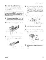
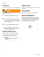
Page 20: ...and a brush whenever removed from gun Be sure to clean the two fluid ports X in the top mating surface Do not damage the flat sealing surfaces Coat with grease if left exposed to seal out moisture WARNING Read warnings page 8 1 Follow Pressure Relief Procedure page 15 2 Flush with compatible solvent into a grounded metal pail holding a metal part of fluid manifold firmly to side of pail Use the lo...

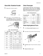
Page 21: ...Spray Mix Chamber Part No Drill Size in mm Mix Chamber Part No Drill Size in mm AR2020 58 042 1 00 AF2020 3 32 094 2 35 AR2929 55 052 1 30 AF2929 3 32 094 2 35 AR3737 55 052 1 30 AR4242 53 060 1 50 AF4242 3 32 094 2 35 AR5252 50 070 1 75 AF5252 3 32 094 2 35 AR6060 44 086 2 15 AR7070 3 32 094 2 35 AR8686 32 0 116 2 90 TI2409A N TI2418A C Table 2 Passage Diameters Passage Description Ref Letter pag...

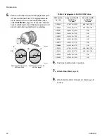
Page 22: ... and AF 4242 or larger CB Table 3 Impingement Port Drill Bit Sizes MixChamber Part No Impingement Port IP Drill Bit Size in mm Counterbore CB Drill Bit Size in mm AR2020 76 020 0 50 53 060 1 50 AR2929 69 029 0 70 53 060 1 50 AR3737 63 037 0 94 N A AR4242 58 042 1 00 N A AR5252 55 052 1 30 N A AR6060 53 060 1 50 N A AR7070 50 070 1 75 N A AR8686 44 086 2 15 N A AF2020 76 020 0 50 53 060 1 50 AF2929...

Page 23: ...n actuates slowly Plugged muffler 22 Clean page 20 Damaged piston o rings 16 17 Replace page 32 Dirty air valve or damaged o rings 24 Clean air valve or replace o rings page 33 Gun delays then actuates abruptly Cured material around side seals 18 Inspect side seals 18c and mix chamber 19 for scratches Replace page 29 Retaining ring 9 not bottomed out Tighten retaining ring until bottomed out Loss ...

Page 24: ...lace page 29 Damaged front o ring 3 Replace page 29 Reduced cleanoff air Damaged front o ring 3 Replace page 29 Excessive cleanoff air when fluid valves are closed and gun is trig gered Damaged missing fluid housing o ring 23 Replace page 29 Fluid does not shut off when fluid valves are closed Damaged fluid valves 12b Replace Burst of air from muffler when gun is triggered Normal No action require...

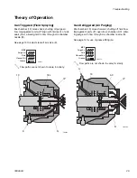
Page 25: ...anoff air valve K Gun Detriggered Air Purging Mix chamber 19 moves forward shutting off fluid flow Impingement ports IP open to air chamber AC allow ing purge air to flow through mix chamber nozzle N See page 14 for use of grease fitting G TI3545a 19 18c IP N K TI3547a KEY Purge Air Fluid Cleanoff Air Grease Flow paths are not shown to scale for clarity TI3546a 19 AC IP N G TI3547a KEY Purge Air F...

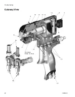
Page 26: ...Troubleshooting 26 309550U Cutaway View 8 19 17 15 16 24 10 23 21 24 14 4 26 18 A Side B Side not shown 12b 22 C G D E F 3 H ...

Page 27: ...e 7 Proper attachment of front end is critical Do not operate gun if front end is loose or lock ring is not snug against handle 1 Follow Pressure Relief Procedure page 15 2 Flush Gun page 20 CAUTION If lock ring R is stuck due to material buildup do not force it by turning entire front end Locating tabs Z may break off Soak front of gun in solvent to soften cured material and free lock ring 3 Unsc...

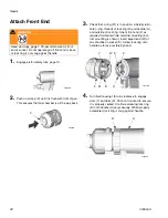
Page 28: ...1 is in position Liberally lubri cate o ring threads of lock ring R and handle H and outside of lock ring Orient front end F as required for desired fluid manifold mounting bot tom mounting is shown Insert keyed end W of mix chamber in socket X Screw lock ring onto handle as far as possible by hand 4 Turn fluid housing 1 8 turn clockwise to engage slots Y and tabs Z Push on front end to ensure it ...

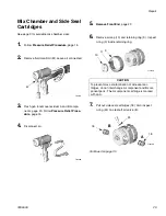
Page 29: ...0 Follow Pressure Relief Proce dure page 15 4 Disconnect air TI2543A M TI2540A 5 Remove Front End page 27 6 Remove air cap 10 and retaining ring 9 Inspect o ring 3 inside retaining ring CAUTION To prevent cross contamination of side seal car tridges do not interchange A component and B com ponent parts The A component cartridge is marked with an A 7 Pull out side seal cartridges 18 Also inspect o ...

Page 30: ... parts The A component cartridge is marked with an A 10 Carefully inspect side seal cartridge o rings and surfaces Replace worn or damaged parts Lib erally lubricate o rings 18d 18e and reassem ble Press on side seal 18c to check proper spring 18b operation B A TI2428A 19 N TI2427A 18e 18c 18d 18b 11 Liberally lubricate and reinstall side seal car tridges 18 12 Lubricate all threads and reinstall ...

Page 31: ...nt parts The A component check valve is marked with an A TI2543A M TI2540A 5 Pry out check valves 26 at notch WARNING Read warnings page 7 Damaged check valve o rings 26f 26g may result in external leakage Replace o rings if any damage is seen 6 Slide filter 26d off Clean and inspect parts Thor oughly inspect o rings 26f 26g If necessary remove screw 26b and disassemble entire check valve 7 Reasse...

Page 32: ...o ring 14 TI2554A M D 5 14 TI2430A 5 Push piston shaft to remove piston 15 Inspect piston o ring 16 and shaft o ring 17 6 Liberally lubricate piston o rings Reinstall piston Shaft is keyed for proper assembly Push firmly to seat piston 7 Install cylinder cap 5 8 Attach Front End page 28 9 Attach fluid manifold Connect air Return gun to service 16 17 15 TI2431A TI2432A TI2430A 5 ...

Page 33: ...ium strength Loctite or equivalent to threads on stop 28 and reassemble 5 Attach fluid manifold Connect air Return gun to service TI2554A M D 5 14 28 24 30 4 TI2433A 1 Follow Pressure Relief Procedure page 15 2 Disconnect air D and remove fluid manifold M 3 Unscrew air valve plug 2 and remove spring 31 Using a small diameter tool push spool 32 out from front Inspect o rings 24 4 Liberally lubricat...

Page 34: ...ee page 36 for additional parts and detail views 35 3 Torque to 125 135 in lb 14 15 N m Torque to 20 30 in lb 2 3 3 4 N m Torque to 235 245 in lb 26 6 27 7 N m Torque to 35 45 in lb 4 5 N m Torque to 32 40 ft lb 43 54 N m 1 2 3 4 5 4 3 5 1 1 1 3 2 2 4 4 4 Check Valve 26 Detail TI3927A 12g 18 see detail above 18 see detail above 26 see detail at right 20 18e 18c 18b 18d 18a Seal Cartridge 18 Detail...

Page 35: ...age of 6 1 17 248134 O RING piston shaft package of 6 1 18 246349 CARTRIDGE seal A side SST includes 18a 18e 1 246350 CARTRIDGE seal B side SST includes 18a 18e 1 18a CARTRIDGE BODY 1 18b 117491 SPRING 1 18c SEAL KIT see page 41 1 18d 248130 O RING cartridge body package of 6 1 18e 248128 O RING side seal package of 6 1 19 CHAMBER mix round see Round Pattern Guns page 37 1 CHAMBER mix flat see Fla...

Page 36: ...r pattern gun only 1 59 15D971 TIP spatter pattern gun only 1 60 248019 SEAL package of 5 spatter pattern gun only 1 61 15F240 ADAPTER stud wall 1 62 15F854 PACKING tip stud wall 1 63 15F241 CAP air stud wall 1 64 FTM979 TIP flat stud wall 1 Ref No Part No Description Qty TI2557A Flat Pattern Detail 19 10 39 40 Spatter Tip Detail 58 59 10 60 TI4555B Flat Pattern Stud Wall Foam Detail TI4660C 1 61 ...

Page 37: ... 1 50 0 042 58 1 00 N A N A AR5252 0 070 50 1 75 0 052 55 1 30 N A N A AR6060 0 086 44 2 15 0 060 53 1 50 N A N A AR7070 0 094 3 32 2 35 0 070 50 1 75 N A N A AR8686 0 116 32 2 90 0 086 44 2 15 N A N A Mix Chamber Kit includes drill bits and o ring Ref No 40 O ring Nozzle Orifice Size Nozzle Drill Bit Size in mm Impingement Port Size Impingement Port Drill Bit Size in mm Counterbore Size Counterbo...

Page 38: ... Pattern Size in mm FT0424 low flow 8 10 203 254 FT0438 medium flow 8 10 203 254 FT0624 low flow 12 14 305 356 FT0638 medium flow 12 14 305 356 FT0838 medium flow 16 18 406 457 FT0848 high flow 16 18 406 457 FT 08 48 FT Flat tip x2 pattern length 8x2 16 in Equivalent orifice diameter size 048 in Ref No Bulk O ring Kits qty 246347 Side Seal Cartridge O ring Kit 246348 Side Seal Kit 246351 Check Val...

Page 39: ...5 6 1 8 125 3 18 246623 3 32 0 116 2 90 246810 3 7 64 0 109 2 77 246813 3 39 099 2 51 246624 3 3 32 094 2 39 246812 3 43 089 2 26 246625 3 44 086 2 18 248639 6 2 15 mm 085 2 15 249114 6 45 082 2 08 246811 3 2 mm 079 2 00 246626 6 50 070 1 78 249113 6 52 0 64 1 63 248893 6 1 16 062 1 59 246627 6 53 060 1 52 249112 6 1 45 mm 057 1 45 246809 6 54 055 1 40 246628 6 55 052 1 32 249764 6 1 20 mm 047 1 2...

Page 40: ...d fluid housing See Clean Passages page 21 246629 6 58 042 1 07 246808 6 60 040 1 02 248640 6 61 039 0 99 248618 6 63 037 0 94 248891 6 66 033 0 84 246807 6 67 032 0 81 246630 6 69 029 0 74 248892 6 70 028 0 71 246815 6 73 024 0 61 276984 6 74 023 0 57 246631 6 76 020 0 51 246816 6 77 018 0 46 246817 6 81 013 0 33 Kit Part No Qty in Kit Drill Bit Size Illustration nominal in mm ...

Page 41: ... Equivalent flow to mix chamber size Nozzle Drill Bit Size in mm Impingement Drill Bit Size in mm AW2222 8 203 2 NA 047 1 20 74 022 0 56 AW2828 15 381 0 Ref AR2929 1 16 062 1 59 70 028 0 71 AW3333 15 381 0 Ref AR3737 53 060 1 52 66 033 0 84 AW3939 16 406 4 Ref AR4242 50 070 1 78 61 039 0 99 AW4646 18 457 2 Ref AR5252 085 2 15 56 046 1 17 AW5757 18 457 2 Ref AR6060 42 089 2 26 1 45 mm 057 1 45 AW64...

Page 42: ...Fusion gun to non Graco D gun hose set 246945 To connect Graco Fusion gun to non Graco heated hose Kit Part No Hole Diameter x Length in mm Recommended Mix Chambers Spray Distance ft m Pattern Diameter in mm 248010 042 x 0 50 1 06 x 12 7 AR2020 AF2929 15 4 57 10 254 248011 052 x 0 50 1 32 x 12 7 AR2929 AF2929 12 3 66 10 254 248012 060 x 0 50 1 52 x 12 7 AR4242 AF4242 12 3 66 12 305 248013 070 x 0 ...

Page 43: ...istant lithium based lubricant MSDS sheet available at www graco com Grease Cartridge for Gun Shutdown 248280 Cartridge 3 oz 10 Specially formulated low viscosity grease flows easily through gun passages to prevent 2 component curing and keep fluid passages clean See page 14 Flushing Manifold 15B817 Manifold Block See ref no 52 page 34 Solvent Flush Canister Kit 248139 1 qt 0 95 liter Solvent Cup ...

Page 44: ...ol 15D234 Designed to fit CeramTip internal dome and flat tip slits Circulation Manifold 246362 Attach to gun fluid manifold to enable preheating of hose See manual 309818 TI4244a End for Air Purge Tips End for Mechanical Purge Tips TI3877a ...

Page 45: ...onnect Nipple A Component ISO Inlet Size 5 JIC 1 2 20 UNF B Component Resin Inlet Size 6 JIC 9 16 18 UNF Sound Pressure 81 1 dB A using AR5252 at 100 psi 0 7 MPa 7 bar Sound Power measured per ISO 9416 2 91 0 dB A using AR5252 at 100 psi 0 7 MPa 7 bar Dimensions 7 5 x 8 1 x 3 3 in 191 x 206 x 84 mm Weight 2 5 lb 1 1 kg Wetted Parts Aluminum stainless steel carbon steel carbide chemically resistant...

Page 46: ...aterial or workmanship repairs will be made at a reasonable charge which charges may include the costs of parts labor and transportation THIS WARRANTY IS EXCLUSIVE AND IS IN LIEU OF ANY OTHER WARRANTIES EXPRESS OR IMPLIED INCLUDING BUT NOT LIMITED TO WARRANTY OF MERCHANTABILITY OR WARRANTY OF FITNESS FOR A PARTICULAR PURPOSE Graco s sole obligation and buyer s sole remedy for any breach of warrant...

Reviews: