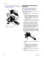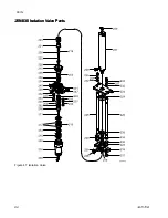
10. To remove and replace the wiper seal (306):
a.
Inside the middle housing (307) on the fluid
side, remove the wiper seal (306). Use pliers
to grip the seal and pull it out.
b.
When replacing the wiper seal (306), make
sure that it is inserted on the fluid side of the
middle housing (307). The diameter of the
fluid side is slightly smaller than the air side
of the housing.
c.
Apply grease to the wiper seal (306) and
snap it into the groove in the middle housing
(307).
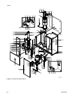
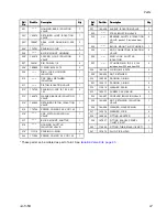
Figure 39 Middle Housing Parts
Reassemble
Reassemble
Reassemble the
the
the Pump
Pump
Pump
1.
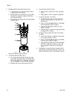
Lay the pump on its side.
2.
Grease the wiper seal (306) in the middle
housing (307).
3.
With the non-sensor end, push the piston rod
(305) through the housing (307). The end must
go through the air side of the housing. (The air
side has the larger diameter.)
4.
Assemble the air piston (316):
a.
Place the o-ring (317) around the air piston
(316) and then grease the o-ring.
b.
Screw the air piston (316) onto the piston rod
(305). Tighten with a wrench on the flats of
the piston rod (305) and a wrench on the flats
of the air piston (316).
c.
When tightened adequately, the white of
the piston rod (305) and the magnet sensor
(314), should protrude slightly from the air
piston (316).
5.
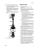
Assemble the fluid piston (301):
a.
Snap the U-cup seal (302) into place on the
fluid piston (301) and then grease the outside
of the U-cup seal.
b.
Screw the fluid piston (301) onto piston rod
(305). Tighten with a wrench on the flats of
the piston rod (305) and wrench on the flats
of the fluid piston (301).
6.
Grease the inside of the air cylinder (319) and
then wiggle it into place over the air piston (316)
and into the middle housing (307).
7.
Push the air piston (316) into the middle housing
(307) so that the fluid piston (301) extends out
of the middle housing.
8.
Grease the inside of the fluid cylinder (310) and
then place either end over the fluid piston (301).
Push it into place into the middle housing (307).
9.
With the fluid cylinder (310) up, orient the pump
so that you are facing the two weep holes in the
middle housing (307). The holes indicate the
front of the system in the isolation cabinet.
10. Place the o-ring (309) onto the fluid cylinder
(310).
11. Place the fluid cover (311) onto the fluid cylinder
(310) so that the holes for the fittings line up with
the weep holes in the middle housing (307).
12. Spin the tie rod screws (312), lock washer (304),
and plain washer (322) into the fluid cover (311).
Tighten in a cross pattern only until snug.
13. Lay the pump on its side to tighten the tie rod
screws (312) in a cross pattern. Torque to 160
in-lb (18 N•m). Tighten the tie rod screws twice
because the plastic pieces relax.
3A7370B
73


