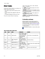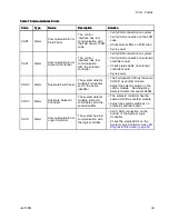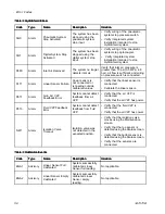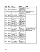
background image

Setup Menus

Maintenance

Maintenance

Maintenance Screens

Screens

Screens

Maintenance

Maintenance

Maintenance 1:

1:

1: Maintenance

Maintenance

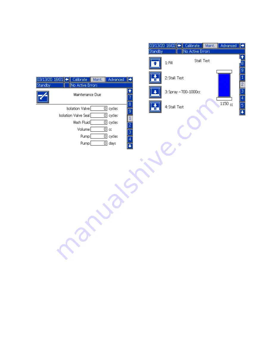
Maintenance Due

Due

Due

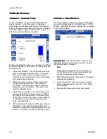
Use the Maintenance Due screen to set maintenance
reminders for system components. When the cycle
counters for each item reach these set values, an
advisory is displayed on the screen.

Isolation

Isolation

Isolation Valve:

Valve:

Valve: The number of times the isolation

valve shuttle has moved.

Isolation

Isolation

Isolation Valve

Valve

Valve Seal:

Seal:

Seal: The number of times the seals

in the housing have been engaged.

Wash

Wash

Wash Fluid:

Fluid:

Fluid: The number of times the wash fluid has

been moved through the isolation valve.

Volume:

Volume:

Volume: The total volume (cc) of fluid dispensed by
the pump between maintenance events. This value
does not account for material that is pushed through
the system in Prime mode.

Pump:

Pump:

Pump: The number of times the pump has dispensed
fluid.

Pump:

Pump:

Pump: The number of days that have passed since
the counter was reset.

Maintenance

Maintenance

Maintenance 2:

2:

2: Pump

Pump

Pump Stall

Stall

Stall Test

Test

Test

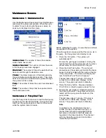
Use the Pump Stall Test screen to test the fluid pump
for internal and external fluid leaks. During the Pump
Stall Test, the pump position is held for 60 seconds
while the system looks for leaks.

Before calibrating the pump, be sure that air and fluid
are supplied to the system.

Prime the system to make sure that there is no air in
the pump. Put the system into Standby mode.

1.

Press the Fill button. The system will
automatically fill.

Be sure the gun trigger is released. During the
test the fluid line will be pressurized to the active
preset value. No air will be sent to the gun.

2.

Press the Stall Test button. The pump will
pressurize and the system will monitor the linear
sensor to look for leaks with the pump at the top
if the pump stroke. The screen will display the
text, "Stall Test" and "Test In Progress."

The test takes about 1 minute. If the test is
successful, a confirmation displays on the
screen. The system will return to Standby.

3.

Press the Spray button. Dispense between
700-1000 cc so that the pump is about 1/4 full.

4.

Be sure the gun trigger is released and press
the Stall Test button. The system will now be
tested with the pump near the bottom of the
pump stroke.

The test takes about 1 minute. If the test is
successful, a confirmation displays on the
screen. The system will return to Standby.

Note

In addition to the HydroShield, this test
checks the hose connections and gun. If
the test fails it should be repeated with the
ball valve on the inlet to the fluid pressure
regulator in the closed position. Then the test
will only check the pump and connections
inside the HydroShield.

3A7370B

45

Summary of Contents for HydroShield WMBH00

Page 1: ...of of of the the the conditions conditions conditions for for for non non non flammability flammability flammability listed listed listed on on on page page page 4 4 4 For For For professional professional professional use use use only only only Important Important Important Safety Safety Safety Instructions Instructions Instructions Read all warnings and instructions in this manual and in the spr...

Page 2: ...ol Interface 32 Menu Bar 33 Soft Key Icons 33 Run Screens and Setup Screens 33 Screen Icons 34 Control Interface Setup and Maintenance 35 Enable USB Data 35 USB Logs 35 System Configuration Settings File 35 Custom Language File 35 Download System Data 36 Upload System Configuration 37 Clean the Screen Surface 37 Run Menus 38 Home Screen 38 Events Screen 39 Status Screen 40 Setup Menus 41 Advanced ...

Page 3: ...Manual Manual No No No Description Description Description 3A7503 Pro Xp Air Assisted WB Gun 309455 Test Fixture High Voltage Probe and kV Meter 312782 Air Actuated Dispense Valve 312794 Merkur Pump Assembly 307273 Fluid Outlet Filter 309227 Gun Flush Box Module 3A7370B 3 ...

Page 4: ...stain burning in accordance with the Standard Test Method for Sustained Burning of Liquid Mixtures ASTM D4206 CE EN CE EN CE EN 50059 50059 50059 Compliant Compliant Compliant Material is classified as non ignitable as defined by EN 50059 2018 For more information see Ignitability of Coating Materials page 98 When an electrostatic gun is connected to a voltage isolation system all of the fluid in ...

Page 5: ... assisted gun for waterborne coatings 25R012 25 ft 7 6 m 25R013 36 ft 10 9 m 25R014 50 ft 15 2 m 25R015 75 ft 22 8 m 25R016 100 ft 30 5 m 235068 6 ft 1 8 m 235069 15 ft 4 6 m 235070 25 ft 7 6 m 235071 36 ft 10 9 m 235072 50 ft 15 2 m 235073 75 ft 22 8 m 235074 100 ft 30 5 m Condition Condition Condition for for for non non non flammability flammability flammability FM FM FM approved approved appro...

Page 6: ...e included included included WMBH20 Pro Xp 60 AA WB spray gun 25 ft hose set 30 1 fluid pressure ratio WMBH00 3000 20 7 207 H60T18 25R012 25 ft 7 6 m 235070 25 ft 7 6 m WMBH40 Pro Xp 60 AA WB spray gun 50 ft hose set 30 1 fluid pressure ratio WMBH00 3000 20 7 207 H60T18 25R014 50 ft 15 2 m 235072 50 ft 15 2 m WMBH41 Pro Xp 60 AA WB spray gun 50 ft hose set Equipped for a gun flush box 30 1 fluid p...

Page 7: ...g Working Working Pressure Pressure Pressure psi psi psi MPa MPa MPa bar bar bar WMBH00 Isolation cabinet for manual air assisted spray 30 1 fluid pressure ratio 3000 20 7 207 WMBH01 Isolation cabinet for manual air assisted spray equipped for gun flush box 30 1 fluid pressure ratio 3000 20 7 207 WMBH04 Isolation cabinet for manual air assisted spray 15 1 fluid pressure ratio 1500 10 3 103 WMBH05 ...

Page 8: ...s non ignitable as defined by EN 50059 2018 Electrostatic equipment must be used only by trained qualified personnel who understand the requirements of this manual Stop Stop Stop operation operation operation immediately immediately immediately if static sparking occurs or you feel a shock Do not use equipment until you identify and correct the problem Check gun resistance hose resistance and elec...

Page 9: ...ischarge Discharge and and and Grounding Grounding Grounding Procedure Procedure Procedure Only use the red colored Graco electrically conductive gun air hose with this gun Do not use black or gray colored Graco air hoses Do not splice hoses together Install only one continuous Graco waterborne fluid hose between the isolated fluid supply and the spray gun MOVING MOVING MOVING PARTS PARTS PARTS HA...

Page 10: ...te hoses and cables away from traffic areas sharp edges moving parts and hot surfaces Do not kink or over bend hoses or use hoses to pull equipment Keep children and animals away from work area Comply with all applicable safety regulations PLASTIC PLASTIC PLASTIC PARTS PARTS PARTS CLEANING CLEANING CLEANING SOLVENT SOLVENT SOLVENT HAZARD HAZARD HAZARD Many solvents can degrade plastic parts and ca...

Page 11: ... Item Item Item Description Description Description A Air Inlet C Control Interface D Air Outlet to Gun E Fluid Outlet to Gun F Fluid Inlet G Isolation Valve J Fluid Inlet Valve K Fluid Pump Item Item Item Description Description Description L Merkur AA Fluid Pump M Electronics Panel N Ground Rod and Bleed Resistor P Power Supply R Hand held Grounded Rod W Wash Fluid Reservoir Z Fluid Filter 60 me...

Page 12: ... Bleed Type Air Valve AM Main Air Supply Line AS Oil Separator AV Air Shut off Valve CA Isolation Cabinet FS Fluid Supply Line FV Fluid Shut off Valve GC Ground Wire GW Pro Xp Waterborne Electrostatic Air Assisted Spray Gun Item Item Item Description Description Description HG Graco Red Grounded Air Hose left hand threads at gun HW Graco Waterborne Fluid Hose LT Light Tower PC Power Cord Required ...

Page 13: ...imize the hose length to the gun Minimizing the hose length minimizes the system charge and discharge time Position the supply pump as close as possible for the fastest fill time Install in a non hazardous location Install Install Install the the the System System System Installing and servicing this equipment requires access to parts which may cause electric shock or other serious injury if work ...

Page 14: ...two people remove the system from the pallet 2 Install the wheels 95 washers 96 and nuts 97 Tighten the nuts securely 3 Install the end plugs 3a 3b 4 When the system is in the desired location lock all four wheels Figure 3 Wheel Mount Parts Mount Mount Mount on on on the the the Wall Wall Wall Before mounting the isolation cabinet to the wall make sure that the wall can support the weight of the s...

Page 15: ...racket can be removed from the isolation cabinet and installed in another location If relocated make sure that the light tower is installed in a non hazardous location and that the painter can see it from the spray booth Longer extension cables are available See Accessories page 92 2 Connect the CAN cable on the light tower LT to the control interface C so that the isolation system can communicate...

Page 16: ... isolation cabinet and a true earth ground The resistance must be less than 100 ohms Fluid supply Ground the fluid supply by connecting a ground wire and clamp See your fluid supply instruction manual for grounding instructions Power supply The power supply is grounded through the power cord to a grounded outlet Spray gun Ground the gun by connecting the red colored Graco grounded air hose HG to t...

Page 17: ...s Hoses Hoses To reduce the risk of electric shock install only one continuous Graco waterborne hose between the isolation cabinet and the gun Do not splice hoses together Always use a Graco waterborne fluid hose between the fluid outlet on the isolation cabinet and the gun fluid inlet When setting up the isolation system for the first time connect the hoses in the following order 1 Fluid hose fro...

Page 18: ... shown The gap between the fitting and the barrel must be less than 125 in 3 2 mm Figure 8 Orientation of Fitting and Barrel 4 Loosen the strain relief nut 101c 5 Apply dielectric grease to the threads of the hose connector 101g Pull the connector back and apply grease to the outside diameter of the hose Thread it into the barrel connector 101 until snug and then a minimum of 1 2 turn more Use a w...

Page 19: ...ir hose between the air outlet D on the isolation cabinet and the gun air inlet swivel on the gun Before beginning this procedure the fluid hose should be attached to the gun barrel and the air inlet swivel should be positioned through the bracket at the gun handle 1 Install and tighten the air hose onto the gun air inlet swivel Note This fitting connection is a left hand thread 2 Connect the air ...

Page 20: ...n and replace it in the cabinet Figure 12 Replacing Wash Fluid Reservoir 6 Close the isolation valve cover 99 and reinstall the electrostatic shield 82 inside the cabinet 7 Close the cabinet door and use a flat blade screwdriver to secure the door shut Connect Connect Connect the the the Air Air Air Supply Supply Supply Hose Hose Hose to to to the the the Cabinet Cabinet Cabinet Use a wrench to co...

Page 21: ... CAN Cables Cables Cables Connect the Control Area Network CAN cables to the control interface so that the interface can communicate with the isolation system 1 Connect the power supply CAN cable a Locate the CAN cable attached to the power supply P on the back of the cabinet b On the right side of the cabinet screw the cable into the fitting labeled Figure 14 Controller CAN Cable Connections on t...

Page 22: ...m is plugged in the control interface powers up in Off mode Figure 16 Power Supply Connections Connect Connect Connect the the the Gun Gun Gun Flush Flush Flush Box Box Box To use a gun flush box with the isolation system requires the following parts Gun Flush Box Module part 244105 Graco manual 309227 included with 244105 Gun Flush Box Adapter Kit for 60 kV and 85 kV Guns part 24N528 5 32 inch tu...

Page 23: ...e System menu check the Gun Flush Box field If this option is not enabled the system does not recognize that the gun flush box is present See System page 50 Check Check Check the the the Grounding Grounding Grounding of of of the the the Spray Spray Spray Gun Gun Gun and and and Isolation Isolation Isolation System System System Megohmmeter Part No 241079 AB in Figure 6 is not approved for use in ...

Page 24: ... wire is connected to a true earth ground If the resistance is still too high replace the air hose Figure 20 Check the Electrical Grounding of the Gun 8 Use an ohmmeter or megohmmeter in the ohm range to measure the resistance between the cabinet ground lug 214 and a true earth ground CC The resistance must be less than 100 ohms Figure 21 Check the Grounding of the Cabinet Flush Flush Flush the th...

Page 25: ... Discharge Discharge Discharge and and and Grounding Grounding Grounding Procedure Procedure Procedure Whenever you are instructed to discharge the voltage Before cleaning flushing or servicing the system equipment Before approaching the front of the gun Before opening the isolation cabinet 1 Release the gun trigger and turn off electrostatics by turning the ES ON OFF valve on the back of the hand...

Page 26: ...he gun trigger and turn off electrostatics by turning the ES ON OFF valve on the back of the handle to the OFF position 2 Engage the trigger lock 3 Follow the Fluid Voltage Discharge and Grounding Procedure page 25 4 Use the control interface to change to Off mode See Control Interface page 32 5 Turn off the air supply and fluid supply to the system 6 Disengage the trigger lock 7 Trigger the gun i...

Page 27: ...ion system were tested in fluid at the factory To avoid contaminating your fluid flush the isolation system with a compatible flushing fluid before you use the equipment Once in operation flush the system after painting Flush the system using Purge mode In Purge mode the air to the gun is shut off and the system dispenses all of the fluid in the fluid cylinder To flush the system Use Purge mode to...

Page 28: ...install the air cap tip guard and retaining ring 16 Hang the gun from its hook with the nozzle pointing down Be sure to keep the gun from grounding out Gun Gun Gun Flush Flush Flush Box Box Box Operation Operation Operation Opening and closing the gun flush box lid could pinch or cut fingers or other body parts Be careful when pressing or releasing the latch knobs and keep clear of the closing lid...

Page 29: ...til performing the Fluid Voltage Discharge and Grounding Procedure page 25 Follow the Fluid Voltage Discharge and Grounding Procedure page 25 when you stop spraying and whenever you are instructed to discharge the voltage 1 Prime the isolation system Follow Prime the Isolation System page 29 2 Set the gun fluid and air settings See Adjust the Gun Fluid and Air Settings page 30 3 Put the system int...

Page 30: ...ht use the best pressure settings for black paint Preset 02 might use the best pressure settings for red paint and Preset 99 might be set to the lowest pressure possible to perform a flush For instructions on creating presets see Presets page 49 To To To use use use Preset Preset Preset 0 0 0 Preset 0 can be changed by the operator at any time during operation 1 Press the right arrow until Home ap...

Page 31: ... navigate to the Preset field 4 Enter the Preset number that you would like to use 5 Press the Enter button to register the value 6 Press the Exit Screen button Shutdown Shutdown Shutdown 1 Discharge the system voltage Follow the Fluid Voltage Discharge and Grounding Procedure page 25 2 Flush the gun Follow Flush the System page 27 3 Follow the Pressure Relief Procedure page 26 4 Press the power b...

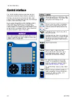
Page 32: ...hen the system is in Off mode press to activate the system This button puts the system into Standby mode Stop Stop Stop Press to stop the system immediately This button puts the system into Off mode and turns off air and fluid to the gun Naviga Naviga Naviga tion tion tion Left Right Arrows Use to move from screen to screen Up Down Arrows Use to move among the fields on a screen to move through th...

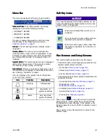
Page 33: ...on Advisory Informational Deviation Important no system shutdown Alarm Very important system shutdown Soft Soft Soft Key Key Key Icons Icons Icons NOTICE NOTICE NOTICE To prevent damage to the softkey buttons do not press the buttons with sharp objects such as pens plastic cards or fingernails Blue icons indicate that a button is not available Gray icons with a green outline indicate that the butt...

Page 34: ...ace Screen Screen Screen Icons Icons Icons Symbols are used to simplify global communication The following descriptions explain what each icon represents Date indicator Time indicator Alarm Event indicator 34 3A7370B ...

Page 35: ...ftware part number and software version System System System Configuration Configuration Configuration Settings Settings Settings File File File The system configuration settings file name is SETTINGS TXT and is stored in the DOWNLOAD folder A system configuration settings file automatically downloads each time a USB flash drive is inserted Use this file to back up system settings for future recov...

Page 36: ...w in the second column Download Download Download System System System Data Data Data 1 Insert the USB flash drive into the USB Port See Connect the CAN Cables page 21 2 The menu bar and USB indicator lights indicate that the USB is downloading files Wait for USB activity to complete A pop up is present until the transfer is complete if it is not acknowledged 3 Remove the USB flash drive from the ...

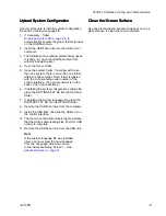
Page 37: ...the control interface The serial number is on the back of the control interface 6 If installing the system configuration settings file place the SETTINGS TXT file into the UPLOAD folder 7 If installing the custom language file place the DISPTEXT TXT file into the UPLOAD folder 8 Remove the USB flash drive from the computer 9 Install the USB flash drive into the USB port on the control interface 10...

Page 38: ...ve G is in the down bottom position In Standby mode the system verifies that there is inlet air supply and that the minimum required 70 psi 0 5 MPa 4 8 bar air pressure is supplied to the system Prime Prime Prime Press to put the system into Prime mode Prime mode is used to load the system with new material Pump volume is minimized and air to the gun is off The system stays grounded Purge Purge Pu...

Page 39: ...ove the minimum required 70 psi 0 5 MPa 4 8 bar Red indicates the system cannot run because the required air pressure is not detected Ground Ground Ground rod rod rod A ground rod icon indicates that the ground rod N is down A charge icon indicates that the ground rod is up and the system is capable of holding a charge Air Air Air Pres Pres Pres sure sure sure Set the air pressure for the gun If t...

Page 40: ...nd purges the system and gun Fluid Fluid Fluid Trigger Trigger Trigger An input or output that is used to turn on fluid to the gun Solenoids Solenoids Solenoids Electrical to pneumatic actuators that drive system activity Shuttle Shuttle Shuttle Down Down Down Drives the isolation valve down and open for filling Shuttle Shuttle Shuttle Up Up Up Drives the isolation valve up and closed for isolatin...

Page 41: ...age Date Date Date Format Format Format Select the desired date format Date Date Date Enter today s date using the number keypad Time Time Time Enter the correct local time 24 hour clock using the number keypad Note The time does not update automatically for local adjustments such as daylight savings time Password Password Password The default password is 0000 Use the number keypad to set a passwo...

Page 42: ...Downloads Uploads Check this field to enable USB download and upload of system information When enabled the Download Depth field becomes active Download Download Download Depth Depth Depth Enter the number of days for which data retrieval is allowed For example to retrieve data for the previous week enter 7 Log Log Log 90 90 90 Full Full Full Advisory Advisory Advisory Enabled Enabled Enabled When...

Page 43: ...t cannot be edited Refer to this screen when updating software or when contacting a Graco distributor for technical assistance Press the magnifying glass button on the upper left to display more information about the system Press the button again to return to the previous screen Scroll to the right to display more information about the system 3A7370B 43 ...

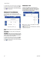
Page 44: ...n This will pressurize the pump and send fluid to the spray gun Pull the gun trigger to dispense fluid In the lower right corner of the screen the pump volume indicator should decrease and the corresponding mV value should increase 4 When fluid stops flowing out of the gun release the trigger Press the Set Empty button The stored mV value will also be displayed next to the button The system will r...

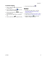
Page 45: ...d for 60 seconds while the system looks for leaks Before calibrating the pump be sure that air and fluid are supplied to the system Prime the system to make sure that there is no air in the pump Put the system into Standby mode 1 Press the Fill button The system will automatically fill Be sure the gun trigger is released During the test the fluid line will be pressurized to the active preset value...

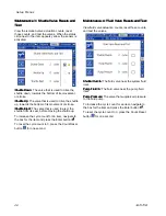
Page 46: ... before moving the shuttle up To increase the cycle count for an item navigate to the box for the item and press the Enter button To reset the cycle count to 0 press the Count Reset button for one second Maintenance Maintenance Maintenance 4 4 4 Fluid Fluid Fluid Valve Valve Valve Resets Resets Resets and and and Test Test Test View fluid valve actuation counts reset those counts and test the valv...

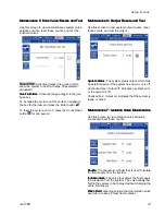
Page 47: ...output counts reset those counts and test the output System System System Status Status Status The system status output which tells an external device if the system has an error or is off Unchecked box Output off indicates a system error or the system is off Checked box Output on indicates that the system is ready or active Maintenance Maintenance Maintenance 7 7 7 Isolation Isolation Isolation Va...

Page 48: ...ll test where the pump position is held for 60 seconds while the system looks for leaks This count is cleared automatically when a pump stall test is computed To increase the cycle count for an item navigate to the box for the item and press the Enter button To reset the cycle count to 0 press the Count Reset button for one second Maintenance Maintenance Maintenance 9 9 9 V2P V2P V2P Use the V2P V...

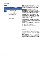
Page 49: ...ough the gun Fluid Fluid Fluid Fluid pressure delivered through the gun Pumps Pumps Pumps Use this screen to enter volume information about the pump Pump Pump Pump Volume Volume Volume The total volume capacity of the pump in cubic centimeters Max Max Max Fill Fill Fill The pump will not fill past this entered value as set by the user Start Start Start Fill Fill Fill The system will not begin to f...

Page 50: ...n trigger is released Default 2 seconds The length of time between when the gun trigger is released and system discharge is a combination of two settings the Ground Rod Delay time and the Fill Start Delay time For example if the Fill Start Delay is set to 7 and the Ground Rod Delay is set to 5 1 The gun trigger is released 2 After 5 seconds the ground rod lowers 3 In 2 more seconds the isolation v...

Page 51: ...nd turn OFF O the ES On Off switch before flushing checking or servicing the system and whenever you are instructed to discharge the voltage Clean all parts with a non flammable fluid as defined under Models page 5 Do not touch the gun nozzle or come within 4 in 102 mm of the nozzle during gun operation or until you perform the Fluid Voltage Discharge and Grounding Procedure page 25 Flush Flush Fl...

Page 52: ...r pump throat seal liquid TSL reservoir 5 Inspect the gun for fluid leaks See your gun manual NOTICE NOTICE NOTICE Any fluid leaking or pooling inside the system can cause low system voltage or arcing that damages system components Clean and dry leaks Replace Replace Replace the the the wash wash wash fluid fluid fluid Check the wash fluid reservoir level W If the level changes service the isolati...

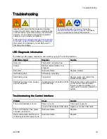
Page 53: ...sis Diagnosis Diagnosis Solution Solution Solution Green on The system is powered up Yellow Internal communication is in progress Red solid Hardware failure Replace module Red flashing fast Software is uploading Red flashing slow Token error Remove token and upload the software token again Red flashes three times pauses and then repeats Invalid rotary switch position FCM and CGM only Change the ro...

Page 54: ...tart Restart When a deviation or alarm occurs be sure to determine the error code before resetting it Go to the Events Screen to view the last 200 errors with date and time stamps See Events Screen page 39 If an alarm has occurred correct the cause before resuming operation To acknowledge a deviation or clear an alarm press Table Table Table 6 6 6 System System System Logic Logic Logic Controller ...

Page 55: ...oller board Check status LEDs on solenoid controller board Cycle power CDD0 Alarm Duplicate Fluid Panel The system detects multiple fluid panels set to the same identifier The fluid panel FCM has the same CAN ID as another module Adjust the selector switch on the control module See Adjusting Selector Switch in manual 3A3954 CDC0 Alarm Duplicate Solenoid Controller The system detects multiple solen...

Page 56: ...tside calibrated values Verify that the linear sensor is connected Calibrate the linear sensor P611 Alarm Gun Air V2P Feedback Error System cannot detect feedback from air V2P Verify that the air V2P is connected Verify that the air V2P has power P613 Alarm Fluid V2P Feedback Error System cannot detect feedback from fluid V2P Verify that the fluid V2P is connected Verify that the air V2P has power...

Page 57: ...huttle down valve MJ21 Advisory Maint Due Valve Shuttle Up Maintenance is due on shuttle up valve MJ31 Advisory Maint Due Valve Shuttle Eject Maintenance is due on shuttle eject valve MJ41 Advisory Maint Due Valve Shuttle Fluid Inlet Maintenance is due on shuttle fluid inlet valve MJ51 Advisory Maint Due Valve Pump Fluid Inlet Maintenance is due on pump fluid inlet valve MJ61 Advisory Maint Due Va...

Page 58: ...plicable EM00 Record System Power Off Record of power cycle OFF Not applicable EC00 Record Setup Value s Changed Record of changing setup variables Not applicable ES00 Advisory Factory Defaults Record of system settings being reset to factory defaults Not applicable EB00 Record Stop Button Pressed Record of stop button press Not applicable WX00 Alarm Software Errors An unexpected software error ha...

Page 59: ...0 full Complete download to ensure no data is lost WSUX Advisory USB Config Err USB configuration file does not match expected checked on startup A software update was not completed successfully Reinstall software EQU0 Advisory USB Idle USB download completed drive may be removed Remove USB device EQU1 Record USB Sys Settings Downloaded Settings were downloaded to USB drive Not applicable EQU2 Rec...

Page 60: ... ES On Off switch before flushing checking or servicing the system and whenever you are instructed to discharge the voltage Clean all parts with a non flammable fluid as defined under Models page 5 Do not touch the gun nozzle or come within 4 in 102 mm of the nozzle during gun operation or until you perform the Fluid Voltage Discharge and Grounding Procedure page 25 Prepare Prepare Prepare the the...

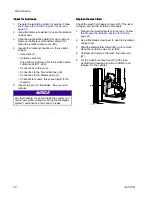
Page 61: ...der a Inlet npsm fitting 72 b Outlet npsm fitting 71 Instead of removing fluid fitting 72 it is also possible to remove the hose 76 from either the air cylinder or from the pump K 10 Disconnect the isolation valve from the cabinet stand 9 On opposing sides of the cabinet stand use a 3 16 inch Allen wrench and a 7 16 inch wrench to remove a The top front and back bolts 23 and washers 19 22 on the i...

Page 62: ...embling the isolation valve you may have indicated the positions of the top and bottom valve sensors If the positions were not indicated use this procedure to determine the positions of the sensors 1 Determine the location of the top sensor a On the control interface enter Off mode Navigate to the Status menu b Raise the isolation valve to the top position c Position the sensor and watch the Statu...

Page 63: ...he o ring groove pointing down away from the air cylinder 227 Slide a new o ring 231 into the groove to hold the shuttle bearing in place c Remove and replace the second shuttle bearing 223 7 Disconnect the shuttle housing 218 assembly from the air cylinder 227 a Locate the flat section on the air cylinder shaft and the flat on the collar b Grip each flat section with an adjustable wrench and turn...

Page 64: ... the nut place the nut and air cylinder in a vise Keep the block mount 224 lined up with the air fitting on the cylinder 4 Use a wrench on the flats on the top of the air cylinder 227 to turn the cylinder until the retaining nut 229 is tight 5 Apply removable thread lock to the threads on the air cylinder 227 shaft 6 Assemble the shuttle housing 218 and the air cylinder 227 a Screw the air cylinde...

Page 65: ...3 Place the sleeve tool 112 over the isolation valve stem 222 and screw onto the housing 201 4 Thread the stem tool 113 into the sleeve tool 112 and tighten to interlock 5 Rotate both tools 112 113 as one to apply pressure to the spring 220 inside When both tools are tightened the valve is opened allowing the valve stem 222 to come out 6 Insert a 3 16 inch Allen wrench into the end of the valve st...

Page 66: ... the groove c From the other end of the valve stem 222 roll the second o ring 228 onto the shaft until it fits into the groove d Grease all 3 o rings Figure 28 Replacing the Isolation Valve O rings 3 Inspect the o ring 219 inside the shuttle housing 218 to make sure that it is still in place 4 To reassemble a Insert the spring 220 and the sleeve 221 wider end first into the sleeve tool 112 Figure ...

Page 67: ...iston seals a Place one U cup 212 onto the piston cap 216 The U cup must face the top shaft of the piston b Place the spacer washer 213 next to the U cup 212 c Place the other U cup 212 onto the piston cap 216 The U cup must face the bottom the retaining cup d Use medium strength thread lock on the retaining cap 214 e Screw the piston cap 216 into the retaining cap 214 f To tighten use an adjustab...

Page 68: ...cup 206 b Grease around the lip of the seal 204 and pop seal side first into place in the housing 201 2 Grease around the o ring 208 and screw into the housing 201 Tighten with a 15 16 inch socket until the retainer 202 bottoms out 3 Insert the piston tool 111 into the piston 211 Grease the sides of the tool especially the top so that it can be pulled past the U cups in the housing assembly 201 mo...

Page 69: ...ve the top housing of the piston cap 210 The housing includes a U cup 203 and an o ring 208 3 Replace the o ring 208 and U cup 203 a Replace the o ring 208 into the groove next to the threading b Replace the U cup 203 where it sinks into place The U cup faces outwards in the cap 4 Remove the spacer U cup 206 and the packing U cup 204 5 Replace the spacer U cup 206 and the packing U cup 204 a On th...

Page 70: ...e from the air fitting 325 7 Remove the two fluid tubes from the fittings 327 at the base of the pump Some residual fluid may leak out 8 A steel bracket holds the pump To remove the pump either Remove the two screws that hold the bracket to the back wall of the cabinet Use a 7 16 inch socket wrench and extension Remove the two screws that hold the bracket to the pump 9 Remove the two base mounting...

Page 71: ...ot cracked 2 Remove the muffler fitting 323 3 Disassemble the fluid section of the pump a Loosen the four tie rod screws 312 with a socket wrench b Sit the pump with the fluid side up and remove the tie rod screws 312 c Lift up and remove the fluid cover 311 and gasket seal 309 d Wiggle the cylinder 310 off of the middle housing 307 e Lay the pump on its side Figure 37 Removing the Fluid Cover 3A7...

Page 72: ...ly grease to the o ring before replacing 7 To remove the piston rod 305 a On the fluid side use a 12 inch wrench on the flats of the piston rod near the fluid piston 301 b Use a 15 inch adjustable wrench on the flats of the fluid piston 301 to loosen c Unscrew the fluid piston 301 off of the piston rod 305 d Push the piston rod 301 through the middle housing 307 to remove 8 To remove the air pisto...

Page 73: ... 5 Assemble the fluid piston 301 a Snap the U cup seal 302 into place on the fluid piston 301 and then grease the outside of the U cup seal b Screw the fluid piston 301 onto piston rod 305 Tighten with a wrench on the flats of the piston rod 305 and wrench on the flats of the fluid piston 301 6 Grease the inside of the air cylinder 319 and then wiggle it into place over the air piston 316 and into...

Page 74: ...erkur manual for details Use this procedure to remove the entire Merkur Pump 75 from the isolation cabinet for service 1 Prepare the isolation system for service Follow the steps under Prepare the Isolation System for Service page 60 2 Use a flat blade screwdriver to open the isolation cabinet door 3 Slide the electrostatic shield 82 up to remove 4 Remove the Merkur electrostatic shield 12 5 Disco...

Page 75: ... Service Service Service the the the Electrical Electrical Electrical Controls Controls Controls Figure 41 Electrical Schematic for 26C896 Electrical Control standard not equipped for gun flush box 3A7370B 75 ...

Page 76: ...Repair Figure 42 Electrical Schematic for 26C716 Electrical Control equipped for gun flush box 76 3A7370B ...

Page 77: ...on Description Part Part Part Number Number Number An 5 32 inch tubing 598095 Bn 3 8 inch tubing 054134 AIR AIR 25E957 25E958 25E961 25E962 FOR CONTROL BOX 26C716 FOR CONTROL BOX 26C896 ISO VIEW MERKUR ISO VIEW MERKUR SWITCH DOOR SECTION AIR AIR VIEW DOOR SWITCH A11 A12 A10 A5 A1 A2 A3 A4 A5 A6 A7 A8 A9 A1 B3 B4 B4 B1 A10 B1 A6 A2 B3 A3 B2 B5 A14 A13 A4 B2 A8 B5 A7 A14 Figure 43 Pneumatic Connecti...

Page 78: ...Notes Notes A8 Used only in systems equipped with a gun flush box A5 Not used A9 Not used A11 Used only in systems equipped with a gun flush box A12 Used only for Pneumatic System Stop Kit when installed 78 3A7370B ...

Page 79: ... SECTION CABLE CABLE kV BOARD 25R197 SPLITTER CABLE 19Y759 INSIDE CONTROL BOX UPPER LOWER INSIDE WALL ISOMETRIC VIEW P2 P3 P4 FOR CONTROL BOX 26C716 FOR CONTROL BOX 26C896 CABLE CABLE UPPER LOWER SIDE WALL ISOMETRIC VIEW INSIDE WALL ISOMETRIC VIEW C2 C3 D2 D1 D6 C2 C1 D3 D4 D5 E2 E2 E1 D4 D5 D3 E3 E4 E5 D7 E1 D6 C3 C1 D1 D2 D1 D2 CONTROL INTERFACE CONTROL INTERFACE Figure 44 Wiring Connections 3A7...

Page 80: ...sembly W4 17B657 Proximity Sensor W5 17B657 Proximity Sensor W6 25R034 Bleed Resistor C1 17D923 Bulkhead Cable C2 121001 CAN Cable ID ID ID Part Part Part No No No Description Description Description C3 17D923 Bulkhead Cable C4 26C774 Power Supply C5 15X472 Light Tower M1 Green Yellow M2 Green Yellow M3 Red M4 Wire Red M5 17G191 Green Yellow 80 3A7370B ...

Page 81: ...Parts Parts Parts Parts Isolation Isolation Isolation System System System Figure 45 Isolation Cabinet 1 See Isolation Cabinet Interior for a detailed view 3A7370B 81 ...

Page 82: ...Parts Figure 46 Isolation Cabinet Interior 82 3A7370B ...

Page 83: ...D ASSY ISO SYS 1 25 17D918 MANIFOLD AIR SPEED CONTROL 1 Ref Ref Ref No No No Part Part Part No No No Description Description Description Qty Qty Qty 26 514930 SCREW CAP SKT HEAD 2 27 158491 FITTING NIPPLE 1 2 NPT 1 28 15T937 FITTING ELBOW 1 4 MNPT X 5 32 T 1 29 157350 Q ADAPTER 3 8 NPT X 1 4 NPT 1 30 119159 SWITCH AIR FLOW 1 31 15T546 FITTING STRAIGHT 3 8 T X 3 8 MNPT 3 32 100022 SCREW CAP HEX HEA...

Page 84: ...SHER FLAT 2 87 111307 WASHER LOCK EXTERNAL 2 Ref Ref Ref No No No Part Part Part No No No Description Description Description Qty Qty Qty 88 SEALANT ANAEROBIC BLUE 1 89 SEALANT PIPE 1 90 PERFORMANCE REQUIREMENT 1 91 590332 TUBE POLY FLO 25OD 040WA 1 92 BAR NEOPRENE STRIP ADHESIVE 2 93 18C026 PLUG HOLE 437 7 94 101566 NUT LOCK 4 95 16F207 CASTER SWIVEL WITH BREAK not shown 4 96 100018 WASHER LOCK S...

Page 85: ... male plug not shown 1 124864 POWER CORD with China Australia AS NZS 3112 male plug not shown 1 129 121056 POWER CORD with Continental Europe CEE 7 7 male plug not shown 1 Ref Ref Ref No No No Part Part Part No No No Description Description Description Qty Qty Qty 130 121818 BULKHEAD TUBE 5 32 INCH on systems WMBH01 WMBH05 WMBH41 WMBH45 1 131 223160 GB FILTER FLUID 1 132 100214 WASHER LOCK 8 Repla...

Page 86: ...Parts 25N030 25N030 25N030 Isolation Isolation Isolation Valve Valve Valve Parts Parts Parts Figure 47 Isolation Valve 86 3A7370B ...

Page 87: ...2 220 17Y486 SPRING COMPR 2 0 X OD 1 22 1 Ref Ref Ref No No No Part Part Part No No No Description Description Description Qty Qty Qty 221 19A448 SLEEVE ISOLATION VALVE 1 222 STEM ISOLATION VALVE 1 223 BEARING SHUTTLE ISOLATION VALVE pack of 2 includes item 231 2 224 BLOCK MOUNT AIR CYLINDER 1 225 ROD CONNECTING ISOLATION VALVE 2 226 RING LOCK SHUTTLE ISOLATION 1 227 CYLINDER AIR ID 2 0 X 10 0 inc...

Page 88: ...Parts 25N031 25N031 25N031 Pump Pump Pump Parts Parts Parts Figure 48 Pump 88 3A7370B ...

Page 89: ... HEX HD 3 8 16 X 7 8 313 HOLDER MAGNET SENSOR 1 Ref Ref Ref No No No Part Part Part No No No Description Description Description Qty Qty Qty 314 15G747 MAGNET LINEAR SENSOR 1 315 160516 PACKING O RING 214 1 316 PISTON AIR ISOLATION PUMP 1 317 17Z468 O RING 346 BUNA N 1 318 111624 PACKING O RING 1 319 17X737 CYLINDER PISTON 4 5 ID 1 320 COVER AIR ISOLATION PUMP 1 321 287839 SENSOR ASSEMBLY 1 322 11...

Page 90: ...Parts Electronic Electronic Electronic Control Control Control Parts Parts Parts Figure 49 Electronic Controls 90 3A7370B ...

Page 91: ...ER 1 433 119162 CONNECTOR PLUG 6 POSITION 3 434 17D921 BRACKET REGULATOR 2 436 RAIL MT CUT TO LENGTH ASSY 0 8 Ref Ref Ref No No No Part Part Part No No No Description Description Description Qty Qty Qty 437 DUCT WIRE 0 55 438 277674 ENCLOSURE CUBE DOOR 1 439 108982 CONNECTOR TUBE 1 440 ADAPTER CABLE CAN IS TO NON IS 2 441 113964 SCREW 4 442 C06061 MUFFLER SINTERED DIA 1 8 2 443 107388 SCREW MACH P...

Page 92: ...Description Description Shielded Shielded Shielded Waterborne Waterborne Waterborne Fluid Fluid Fluid Hose Hose Hose 25R012 25 ft 7 6 m 25R013 36 ft 11 m 25R014 50 ft 15 m 25R015 75 ft 23 m 25R016 100 ft 30 5 m Light Light Light Tower Tower Tower Extension Extension Extension Cables Cables Cables Part Part Part No No No Description Description Description Qty Qty Qty 124003 CABLE CAN MALE FEMALE 5...

Page 93: ...1 19A448 SLEEVE ISOLATION VALVE 1 222 STEM ISOLATION VALVE 1 228 18B106 O RING 109 FX75 2 230 106258 PACKING O RING 1 Kit Kit Kit 26B402 26B402 26B402 Housing Housing Housing Assembly Assembly Assembly Ref Ref Ref No No No Part Part Part No No No Description Description Description Qty Qty Qty 201 HOUSING BASE ISOLATION VALVE 1 205 BLOCK MOUNT HOUSING 1 207 19A381 CAP PISTON ISOLATION VALVE 1 209 ...

Page 94: ...acement Replacement Be careful not to drop or scratch these parts when handling This kit requires tools 111 113 to install See Isolation System page 81 Ref Ref Ref No No No Part Part Part No No No Description Description Description Qty Qty Qty 219 111316 PACKING O RING 2 222 STEM ISOLATION VALVE 1 228 18B106 O RING 109 FX75 2 Kit Kit Kit 26B408 26B408 26B408 Mount Mount Mount Block Block Block Ai...

Page 95: ...PACKING U CUP ID 1 25 X 0D 1 63 2 219 111316 PACKING O RING 2 228 18B106 O RING 109 FX75 2 230 106258 PACKING O RING 1 Kit Kit Kit 26B411 26B411 26B411 Shuttle Shuttle Shuttle Assembly Assembly Assembly Ref Ref Ref No No No Part Part Part No No No Description Description Description Qty Qty Qty 207 194381 PIN DOWEL 1 8 INCH 1 217 BLOCK MOUNT SHUTTLE 1 218 HOUSING SHUTTLE ISOLATION VALVE 1 219 1113...

Page 96: ...M200 WETCUP COVER 1 313 HOLDER MAGNET SENSOR 1 Ref Ref Ref No No No Part Part Part No No No Description Description Description Qty Qty Qty 314 15G747 MAGNET LINEAR SENSOR 1 315 160516 PACKING O RING 214 1 Kit Kit Kit 26B423 26B423 26B423 Fluid Fluid Fluid Cylinder Cylinder Cylinder Ref Ref Ref No No No Part Part Part No No No Description Description Description Qty Qty Qty 309 15G881 SEAL GASKET ...

Page 97: ...nlet 100 psi 7 MPa 6 9 bar 80 psi 6 MPa 5 5 bar 60 psi 4 MPa 4 1 bar 40 psi 3 MPa 2 8 bar Table Table Table 13 13 13 Fill Fill Fill Time Time Time Based Based Based on on on Viscosity Viscosity Viscosity and and and Dynamic Dynamic Dynamic Inlet Inlet Inlet Pressure Pressure Pressure FILL FILL FILL TIME TIME TIME seconds VISCOSITY VISCOSITY VISCOSITY CENTIPOISE CENTIPOISE CENTIPOISE 3A7370B 97 ...

Page 98: ...ight where H2O water LM the entire liquid phase including liquids with flash points above 60 C and those liquids not not not listed in the safety data sheet in which case the entire liquid phase is ignitable in the sprayed state ORG solid phase which is ignitable in the sprayed state ignitable inorganic or ignitable organic solids including the solids which have an ignitable inorganic or ignitable...

Page 99: ...2 in 92 1 cm C1 65 3 in 165 9 cm C2 69 9 in 177 6 cm D1 23 5 in 59 7 cm D2 24 3 in 61 8 cm E 24 3 in 61 6 cm F 39 8 in 101 1 cm Reference Reference Reference U S U S U S Metric Metric Metric G 35 5 in 85 1 cm H 38 5 in 97 8 cm J 48 9 in 124 1 cm K1 63 7 in 161 9 cm K2 59 1 in 150 1 cm L 19 2 in 48 9 cm M 44 3 in 112 4 cm 3A7370B 99 ...

Page 100: ...d Power measured per ISO Standard 9216 at 40 psi 90 4 dB A at 100 psi 105 4 dB A at 0 28 MPa 2 8 bar 90 4 dB A at 0 7 MPa 7 0 bar 105 4 dB A Sound Pressure measured 1 m from gun at 40 psi 87 0 dB A at 100 psi 99 0 dB A at 0 28 MPa 2 8 bar 87 0 dB A at 0 7 MPa 7 0 bar 99 0 dB A Gun Air Outlet Fitting 1 4 npsm m Gun Fluid Outlet Fitting 1 4 NPSM Isolation System Air Inlet Fitting 1 2 npt Isolation S...

Page 101: ...luded North America NEMA 5 15 male plug China Australia AS NZS 3112 male plug Continental Europe CEE 7 7 male plug External Power Requirements 100 240VAC 50 60Hz 2 amp maximum draw 15 amp maximum circuit breaker recommended California California California Proposition Proposition Proposition 65 65 65 CALIFORNIA CALIFORNIA CALIFORNIA RESIDENTS RESIDENTS RESIDENTS WARNING WARNING WARNING Cancer and ...

Page 102: ... WARRANTY WARRANTY WARRANTY AND AND AND DISCLAIMS DISCLAIMS DISCLAIMS ALL ALL ALL IMPLIED IMPLIED IMPLIED WARRANTIES WARRANTIES WARRANTIES OF OF OF MERCHANTABILITY MERCHANTABILITY MERCHANTABILITY AND AND AND FITNESS FITNESS FITNESS FOR FOR FOR A A A PARTICULAR PARTICULAR PARTICULAR PURPOSE PURPOSE PURPOSE IN IN IN CONNECTION CONNECTION CONNECTION WITH WITH WITH ACCESSORIES ACCESSORIES ACCESSORIES ...

Reviews: