Warnings
2
3A5565B
Warnings
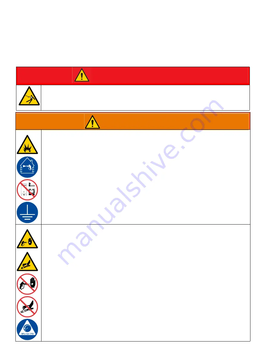
The following warnings are for the setup, use, grounding, maintenance, and repair of this equipment. The exclamation point symbol
alerts you to a general warning and the hazard symbols refer to procedure-specific risks. When these symbols appear in the body
of this manual or on warning labels, refer back to these Warnings. Product-specific hazard symbols and warnings not covered in
this section may appear throughout the body of this manual where applicable
.
DANGER
ELECTROCUTION HAZARD
To avoid death or serious injury, avoid contact with power lines.
WARNING
FIRE AND EXPLOSION HAZARD
Flammable fumes, such as solvent and paint fumes, in
work area
can ignite or explode. Paint or
solvent flowing through the equipment can cause static sparking. To help prevent fire and explosion:
•
Use equipment only in well-ventilated area.
•
Eliminate all ignition sources; such as pilot lights, cigarettes, portable electric lamps, and plastic drop
cloths (potential static sparking).
•
Ground all equipment in the work area. See
Grounding
instructions in the gun manual.
•
Never spray or flush solvent at high pressure.
•
Keep work area free of debris, including solvent, rags and gasoline.
•
Do not plug or unplug power cords, or turn power or light switches on or off when flammable fumes
are present.
•
Use only grounded hoses.
•
Hold gun firmly to side of grounded pail when triggering into pail. Do not use pail liners unless they
are anti-static or conductive.
•
Stop operation immediately
if static sparking occurs or you feel a shock
.
Do not use equipment
until you identify and correct the problem.
•
Keep a working fire extinguisher in the work area.
SKIN INJECTION HAZARD
High-pressure spray is able to inject toxins into the body and cause serious injury that can result in
amputation. In the event that injection occurs,
get immediate surgical treatment.
•
Do not aim the gun at, or spray any person or animal.
•
Keep hands and other body parts away from the discharge. For example, do not try to stop leaks with
any part of the body.
•
Always use the nozzle tip guard. Do not spray without nozzle tip guard in place.
•
Use Graco nozzle tips.
•
Use caution when cleaning and changing nozzle tips. In the case where the nozzle tip clogs while
spraying, follow the
Pressure Relief Procedure
for turning off the unit and relieving the pressure
before removing the nozzle tip to clean.
•
Equipment maintains pressure after power is shut off.
Do not leave the equipment energized or
under pressure while unattended.
Follow the
Pressure Relief Procedure
when the equipment is
unattended or not in use, and before servicing, cleaning, or removing parts.
•
Check hoses and parts for signs of damage. Replace any damaged hoses or parts.
•
This system is capable of producing 7250 psi (500 bar, 50 MPa). Use Graco parts or accessories that
are rated a minimum of 7250 psi (500 bar, 50 MPa).
•
Always engage the trigger lock when not spraying. Verify the trigger lock is functioning properly.
•
Verify that all connections are secure before operating the unit.
•
Know how to stop the unit and bleed pressure quickly. Be thoroughly familiar with the controls.


