Setup
3A5565B
3
Setup
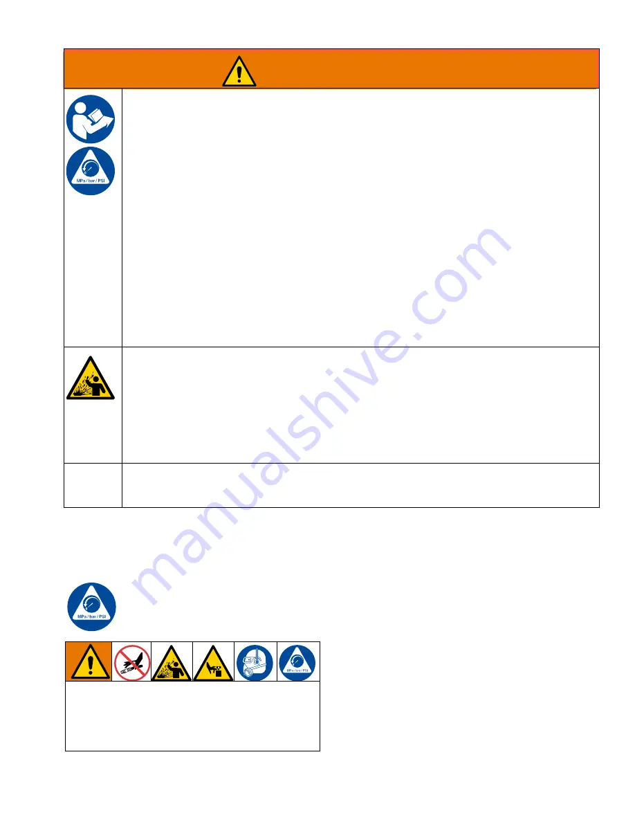
Pressure Relief Procedure
Follow the Pressure Relief Procedure
whenever you see this symbol.
1. Engage trigger lock.
2. Shut off pump.
3. Disengage trigger lock.
4. Hold the metal extension firmly to a grounded metal
pail. Trigger the gun to relieve pressure.
5. Engage trigger lock.
6. Open fluid drain valve (see
System Require-
ments
). Leave drain valve open.
7. If you suspect the spray tip or hose is clogged or
that pressure has not been fully relieved, follow the
steps below and see
:
a. VERY SLOWLY loosen tip guard retaining nut
or hose end coupling to relieve pressure
gradually.
b. Loosen nut or coupling completely.
c. Clear hose or tip obstruction.
EQUIPMENT MISUSE HAZARD
Misuse can cause death or serious injury.
•
Do not operate the unit when fatigued or under the influence of drugs or alcohol.
•
Do not exceed the maximum working pressure or temperature rating of the lowest rated system
component. See
Technical Specifications
in all equipment manuals.
•
Use fluids and solvents that are compatible with equipment wetted parts.
See
Technical Specifications
in all equipment manuals. Read fluid and solvent manufacturer’s
warnings. For complete information about your material, request Safety Data Sheets (SDSs) from
distributor or retailer.
•
Do not leave the work area while equipment is energized or under pressure.
•
Turn off all equipment and follow the
Pressure Relief Procedure
when equipment is not in use.
•
Check equipment daily. Repair or replace worn or damaged parts immediately with genuine
manufacturer’s replacement parts only.
•
Do not alter or modify equipment. Alterations or modifications may void agency approvals and create
safety hazards.
•
Make sure all equipment is rated and approved for the environment in which you are using it.
•
Use equipment only for its intended purpose. Call your distributor for information.
•
Route hoses and cables away from traffic areas, sharp edges, moving parts, and hot surfaces.
•
Do not kink or over bend hoses or use hoses to pull equipment.
•
Keep children and animals away from work area.
•
Comply with all applicable safety regulations.
PRESSURIZED ALUMINUM PARTS HAZARD
Use of fluids that are incompatible with aluminum in pressurized equipment can cause serious
chemical reaction and equipment rupture. Failure to follow this warning can result in death, serious
injury, or property damage.
•
Do not use 1,1,1-trichloroethane, methylene chloride, other halogenated hydrocarbon solvents or
fluids containing such solvents.
•
Do not use chlorine bleach.
•
Many other fluids may contain chemicals that can react with aluminum. Contact your material
supplier for compatibility.
CALIFORNIA PROPOSITION 65
This product contains a chemical known to the State of California to cause cancer, birth defects or
other reproductive harm. Wash hands after handling.
WARNING
This equipment stays pressurized until pressure is man-
ually relieved. To help prevent serious injury from pres-
surized fluid, such as skin injection, splashing fluid and
moving parts, follow the Pressure Relief Procedure
when you stop spraying and before cleaning, checking,
or servicing the equipment.


