background image

DataTrak Operation 

20

313255F

DataTrak Operation

NOTE: The display (AE) will turn off after 1 minute to 
save battery life. Press any key to wake up the display.

Setup Mode

1.

See F

IG

. 8. Press and hold 

 for 5 seconds until 

Setup menu appears.

2.

To enter settings for runaway (if equipped), lower 
size, and flow rate units, and to enable runaway, E1, 

E2, and E5 error options, press 

 to change the 

value, then

 to save the value and move the cur-

sor to the next data field. See page 22 for a descrip-
tion of E1, E2, and E5 error codes.

NOTE: Graco recommends setting runaway (if 

equipped) to 60 

.

NOTE: When runaway, E1, E2, and E5 error options are 
enabled, a 

 will appear on the setup screen.

See F

IG

. 8.

3.

Move the cursor to the E5 error enable option field, 

then press 

 once more to exit Setup mode.

Run Mode

Runaway

NOTE: DataTrak is available with and without runaway 
protection. Packages with M02xxx air motors ship with-
out a runaway solenoid. All other DataTrak packages are 
equipped with a runaway solenoid.

1.

See F

IG

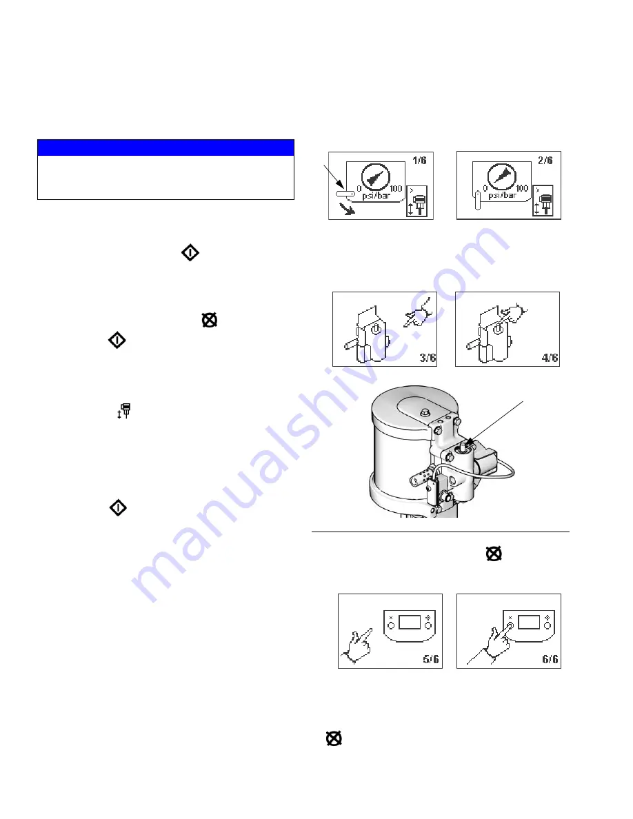
. 8. If pump runaway occurs, the runaway 

solenoid will actuate, stopping the pump. The LED 
(AD) will flash and the display (AE) will indicate a 
runaway condition (see Table 1). The display will 
cycle through six instruction screens.

2.

Runaway Screens 1 and 2: To reset the runaway 
solenoid, close the master air valve (E). Wait for air 
to completely bleed off the air motor.

3.

Runaway Screens 3 and 4: After the air is bled off, 
push the solenoid release button (J) down to reset 
the air valve. The button will pop back up when the 
air valve is repressurized.

4.

Runaway Screens 5 and 6: Press 

 to clear the 

diagnostic code and reset the runaway solenoid.

5.

Open master air valve (E) to restart pump.

NOTE: To disable runaway monitoring, go to setup 
mode and set runaway value to 0 (zero) or toggle (RT) 

off (see 

F

IG

. 8).

NOTICE

To prevent damage to the soft key buttons, do not press 
the buttons with sharp objects such as pens, plastic 
cards, or fingernails.

F

IG

. 9. Solenoid Release Button

J

ti11902a

Summary of Contents for Merkur 313255F

Page 1: ...materials in hazardous or non hazardous locations For professional use only See page 5 for model information including maximum working pressures and approvals Important Safety Instructions Read all warnings and instructions in this manual Save these instructions Model G30W82 Model G28C18 ti13016a ti13017a ll 2 G c T2 ...

Page 2: ...ubleshooting 18 DataTrak Controls and Indicators 19 DataTrak Operation 20 Setup Mode 20 Run Mode 20 Replace DataTrak Battery or Fuse 23 Parts 24 G28xxx Models 26 G30xxx Models 27 G48Wxx Models 28 Kits 29 Wall Mount Kit 24A578 29 Heated Cart Mount Kit 256427 29 Pump and Gun Control Panel Kit 30 Pump Only Control Panel Kit 31 DataTrak Kits 32 PTFE Suction Hose Kits 32 Wall Bracket Mounting Dimension...

Page 3: ...en triggering into pail If there is static sparking or you feel a shock stop operation immediately Do not use equipment until you identify and correct the problem Keep a working fire extinguisher in the work area ELECTRIC SHOCK HAZARD This equipment must be grounded Improper grounding setup or usage of the system can cause electric shock Turn off and disconnect power at main switch before disconne...

Page 4: ...ulations MOVING PARTS HAZARD Moving parts can pinch or amputate fingers and other body parts Keep clear of moving parts Do not operate equipment with protective guards or covers removed Pressurized equipment can start without warning Before checking moving or servicing equipment follow the Pressure Relief Procedure in this manual Disconnect power or air supply TOXIC FLUID OR FUMES HAZARD Toxic flu...

Page 5: ...nting W and the components shown for 80 in the table on page 6 G 30 W 80 First Digit Second and Third Digits Ratio Fourth Digit Mounting Type Fifth and Sixth Digit Components Included G Merkur Package 28 28 1 C Cart See Tables page 6 30 30 1 W Wall 48 48 1 ti12326a ti12327a Wall mount ID Cart mount ID Conforms to FM std 3600 3610 for use in Class I Div 1 Group D T3C Hazardous locations 0359 II 1 G...

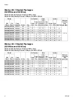
Page 6: ...lter DataTrak G28W07 G28C05 W28EAS 120V XTR 2 0 7 5 G28W08 G28C06 W28EBS 120V XTR G28W09 G28C07 W28EAS 240V XTR G28W10 G28C08 W28EBS 240V XTR G28W17 G28C15 W28EAS 120V G40 G28W18 G28C16 W28EBS 120V G40 G28W19 G28C17 W28EAS 240V G40 G28W20 G28C18 W28EBS 240V G40 Model Pump Assembly Heater Gun Air Controls Hose Options Maximum Fluid Flow Rate gpm lpm Wall Mount Cart Mount Pump Only Pump and Gun Gun ...

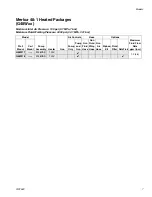
Page 7: ...Fluid Working Pressure 4800 psi 33 1 MPa 331 bar 0 Model Pump Assembly Heater Gun Air Controls Hose Options Maximum Fluid Flow Rate gpm lpm Wall Mount Cart Mount Pump Only Pump and Gun Gun Fluid Hose Gun Fluid Whip Hose Gun Air Hose Siphon Kit Fluid Filter DataTrak G48W17 W48CAS 120V 1 2 4 5 G48W18 W48CBS 120V ...

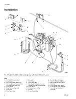
Page 8: ...K Fluid Whip Hose L Electrically Conductive Air and Heated Fluid Supply Return Hose M 3 Way Valve N Suction Hose and Tube P Strainer R Pump Ground Wire S Gun Air Pressure Gauge T Gun Air Pressure Regulator U Bleed Type Master Air Valve V DataTrak W Pump Air Pressure Gauge X Pump Air Pressure Regulator Y Insert for models without DataTrak FIG 1 Typical Installation Your package may not include all ...

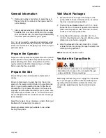
Page 9: ... Wall Mount Packages 1 Be sure the wall can support the weight of the pump bracket hoses and accessories as well as the stress caused during operation 2 Position the wall bracket about 4 5 ft 1 2 1 5 m above the floor For ease of operation and service make sure the pump air inlet fluid inlet and fluid outlet ports are easily accessible 3 Using the wall bracket as a template drill 0 4 in 10 mm moun...

Page 10: ...l J allows for freer gun movement The suction hose N with strainer P allows the pump to draw fluid from a 5 gallon 19 liter pail A fluid filter F with a 60 mesh 250 micron stain less steel element filters particles from fluid as it leaves the pump DataTrak V provides pump diagnostics and mate rial usage information See page 19 The back pressure regulator E controls pressure back to the gun and mai...

Page 11: ...n a nonconductive surface such as paper or card board which interrupts the grounding continuity 9 To maintain grounding continuity when flushing or relieving pressure hold a metal part of the spray gun firmly to the side of a grounded metal pail then trigger the gun Setup Wall Mount Electrical Connections Follow all directions and requirements in the Viscon HP Heater manual 309524 Cart Mount Hazar...

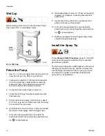
Page 12: ...tach gun swivel J to the gun fluid inlet 4 Attach one end of the fluid whip hose K to the gun swivel and the other end to the recirculating mani fold 5 Attach one blue fluid hose to the recirculating mani fold and to the back pressure regulator E 6 Attach the other blue fluid hose to the recirculating manifold and to the filter F outlet 7 Apply lens cover to both regulator gauge lenses 8 Verify th...

Page 13: ...The gun fluid filter or the fluid hose may be com pletely clogged Very slowly loosen the hose end coupling at the gun and relieve pressure gradually Then loosen completely to clear the obstruction c After following the steps above if the spray tip or hose still seems completely clogged very slowly loosen the tip guard retaining nut or hose end coupling and relieve pressure gradually then loosen co...

Page 14: ...gger open 7 Units with runaway protection only enable the prime flush function by pushing the prime flush but ton on the DataTrak 8 Open bleed type air valve U Slowly turn pump air regulator X clockwise increasing pressure until pump starts 9 Cycle pump slowly until all air is pushed out and pump and hoses are fully primed 10 Units with runaway protection only disable the prime flush function by p...

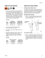
Page 15: ...s with Airless Guns The spray tip orifice and spray angle determine pattern coverage and size When you need more coverage use a larger spray tip rather than increasing fluid pressure Align guard horizontally to spray a horizontal pattern Align guard vertically to spray a vertical pattern Packages with AA Guns 1 See FIG 6 Close off pattern adjustment air by turn ing knob AA clockwise in all the way...

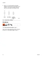
Page 16: ...n is still not narrow enough increase air pressure to gun slightly or use different size tip Shutdown Follow Pressure Relief Procedure page 13 Always flush the pump before the fluid dries on the dis placement rod See Flush the Pump on page 17 FIG 7 Spray Pattern Problems no air too little air correct amount of air ti0792A ...

Page 17: ...id you are pumping and with the wetted parts in your system Check with your fluid manufacturer or supplier for recommended flushing fluids and flushing frequency 1 Follow Pressure Relief Procedure page 13 2 Remove tip guard and spray tip from gun Refer to separate gun manual 3 Place siphon tube in grounded metal pail containing cleaning fluid 4 Set pump to lowest possible fluid pressure and start ...

Page 18: ...nt rod Clean always stop the pump at the bottom of its stroke keep the wet cup 1 3 filled with Graco throat seal liquid TSL Dirty worn or damaged air motor parts Clean or repair air motor See manual 312796 Pump operates but output is low on both strokes Restricted line or inadequate air sup ply closed or clogged valves Clear line or increase air supply Check that the valves are open Obstructed flu...

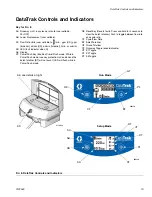
Page 19: ...h mode While in Prime Flush mode runaway protection is disabled and the batch totalizer BT will not count LED will flash while in Prime Flush mode RK Reset Key Resets faults Press and hold for 3 seconds to clear the batch totalizer Push to toggle between flow rate and cycle rate CF Cycle Flow Rate BT Batch Totalizer GT Grand Totalizer RT Runaway Toggle enable disable UT E1 Toggle DT E2 Toggle ST E...

Page 20: ...otors ship with out a runaway solenoid All other DataTrak packages are equipped with a runaway solenoid 1 See FIG 8 If pump runaway occurs the runaway solenoid will actuate stopping the pump The LED AD will flash and the display AE will indicate a runaway condition see Table 1 The display will cycle through six instruction screens 2 Runaway Screens 1 and 2 To reset the runaway solenoid close the m...

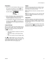
Page 21: ...t to liters or cc BT and GT display liters If AC is set to cycles BT and GT display cycles Press to toggle between flow rate units and cycles A letter under the BT display indicates that both BT and GT are displaying gallons g or liters l No letter means both BT and GT are displaying cycles Display See FIG 8 The display AE will turn off after 1 minute of inactivity in Run mode or 3 minutes in Setu...

Page 22: ... protection may be enabled with pump that is not equipped with a runaway solenoid valve Enter setup screen and disable runaway pro tection E 4 Disconnected Solenoid units with runaway protection only Solenoid is disconnected Solenoid unplugged Damaged solenoid wires Solenoid is not engaging piston cup 112 Bracket and solenoid not tight against air valve housing E 5 Service Component 2 Problem with...

Page 23: ...e 1 Remove the screw metal strap and plastic holder 2 Pull the fuse away from the board 3 Replace with a new fuse The battery and fuse must be replaced in a non hazardous location Use only the following approved replacement batter ies Use of an unapproved battery will void Graco s warranty and FM and Ex approvals Ultralife lithium U9VL Duracell alkaline MN1604 Energizer alkaline 522 Varta alkaline...

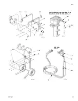
Page 24: ...vary by model See Parts Lists on pages 26 to 28 64 67 67 63 62 66 84 64 1 60 61 75 69 70 71 72 4 5 83a 83b 6 74 73 81 82 77 2 3a 3b ti13018a wallmount models cart mount models 48 76 G48xxx Models G28xxx and G30xxx Models 85 86 77 76 76 ...

Page 25: ...Parts 313255F 25 65 9 22 10 8 G40 Gun Shown ti13111a ti13143a ti13114a 16 16 Non Hazardous Location Electrical Cord Parts 120V Cart Mount Only 79 80 65 49 54 53 68 ti13261a 60 60 78 120V only 50 51 ...

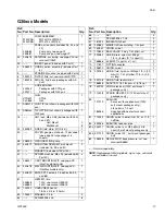
Page 26: ... KIT see page 29 GxxCxx models only 1 54 24A578 WALL MOUNTING KIT see page 29 GxxWxx models only 1 60 24A590 BRACKET heated kit includes 64 65 and 66 1 61 245848 245863 HEATER fluid 120V see manual 309524 240V see manual 309524 1 62 100022 CAPSCREW hex hd 1 4 20 x 3 4 in 19mm 2 63 100527 WASHER 1 4 in 2 64 SCREW M8 x 25 8 65 NUT 4 66 SCREW M8 x 1 25 4 67 167002 INSULATOR heat 4 68 239864 MANIFOLD ...

Page 27: ...RT MOUNTING KIT see page 29 GxxCxx models only 1 54 24A578 WALL MOUNTING KIT see page 29 GxxWxx models only 1 60 24A590 BRACKET heated kit includes 64 65 and 66 1 61 245848 245863 HEATER fluid 120V see manual 309524 240V see manual 309524 1 62 100022 CAPSCREW hex hd 1 4 20 x 3 4 in 19mm 2 63 100527 WASHER 1 4 in 2 64 SCREW M8 x 25 8 65 NUT 4 66 SCREW M8 x 1 25 4 67 167002 INSULATOR heat 4 68 23986...

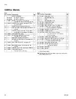
Page 28: ...art 49 4 54 24A578 WALL MOUNTING KIT see page 29 1 60 24A590 BRACKET heated kit includes 64 65 and 66 1 61 245848 HEATER fluid 120V see manual 309524 1 62 100014 CAPSCREW hex hd 1 4 20 x 1 25 in 31 mm 2 63 100527 WASHER 1 4 in 2 64 SCREW M8 x 25 8 65 NUT 4 66 SCREW M8 x 1 25 4 67 167002 INSULATOR heat 4 69 15V522 UNION swivel 1 70 113834 BALL VALVE 3 way 1 4 npt m sst 1 71 239062 HOSE drain nylon ...

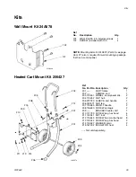
Page 29: ...2 209 203 207 ti13357a 206 205 204 208 Not sold separately Ref No Part No Description Qty 201 CART frame 1 202 HANDLE cart 1 203 119451 WHEEL semi pneumatic 2 204 119452 CAP hub 2 205 277790 SLEEVE cart handle 1 206 15C871 CAP leg 2 207 115480 KNOB t handle 2 208 116630 SCREW carriage 2 209 BRACKET heater cart 1 210 111799 SCREW cap hex head 4 211 104541 NUT lock 4 212 115643 SCREW hex washer head...

Page 30: ...1 306 15T937 ELBOW swivel 5 32 T x 1 4 npt 1 307 TUBE black cut to fit order Tubing Kit 24D496 4 in 308 15T498 SWIVEL 90 5 32T x 1 8 npt f 2 309 15T866 ELBOW swivel 5 32T x 1 8 npt 1 310 15T500 GAUGE pressure 2 311 113498 VALVE safety 1 312 164672 ADAPTER 1 313 15T538 NUT regulator 1 314 114381 SCREW cap button head 2 315 15T539 REGULATOR air gun 3 8 npt 1 316 116514 NUT regulator 1 317 15T555 PAN...

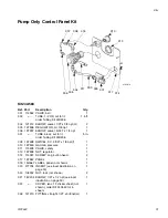
Page 31: ...pt 1 307 TUBE black cut to fit order Tubing Kit 24D496 5 in 308 15T498 SWIVEL 90 5 32T x 1 8 npt f 1 310 15T500 GAUGE pressure 1 311 113498 VALVE safety 1 313 15T538 NUT regulator 1 314 114381 SCREW cap button head 2 317 15T557 PANEL 1 318 15U667 LABEL panel not shown 1 319 277794 INSERT see inset illustration on page 30 1 320 105332 NUT lock not shown 2 321 15V204 ELBOW 1 2T x 1 2 npt see inset i...

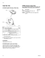
Page 32: ...id Provides monitoring and diagnostics without runaway protection PTFE Suction Hose Kits For pumping acid materials that are compatible with PTFE Includes suction hose swivel and strainer Ref No Part No Description Qty 401 24B563 DATATRAK assembly includes Part 3 1 402 24B566 SOLENOID REED SWITCH kit 1 403 CLAMP hose not shown Order kit 24A548 for pack age of 10 2 404 15V262 LABEL warning not show...

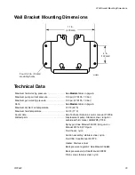
Page 33: ...Maximum fluid temperature 160 F 71 C Sound data See Technical Data in air motor manual 312796 Wetted parts Displacement pump Stainless steel tungsten carbide with 6 nickel UHMWPE PTFE Spray gun See Manual 3A0149 AA guns or Manual 312145 XTR gun Fluid hoses nylon Suction assembly stainless steel nylon Fluid filter See Manual 307273 Heater Stainless steel Back pressure regulator See Manual 306860 Ba...

Page 34: ...al or workmanship repairs will be made at a reasonable charge which charges may include the costs of parts labor and transportation THIS WARRANTY IS EXCLUSIVE AND IS IN LIEU OF ANY OTHER WARRANTIES EXPRESS OR IMPLIED INCLUDING BUT NOT LIMITED TO WARRANTY OF MERCHANTABILITY OR WARRANTY OF FITNESS FOR A PARTICULAR PURPOSE Graco s sole obligation and buyer s sole remedy for any breach of warranty sha...

Reviews: