background image

Repair 

26

3A0732U

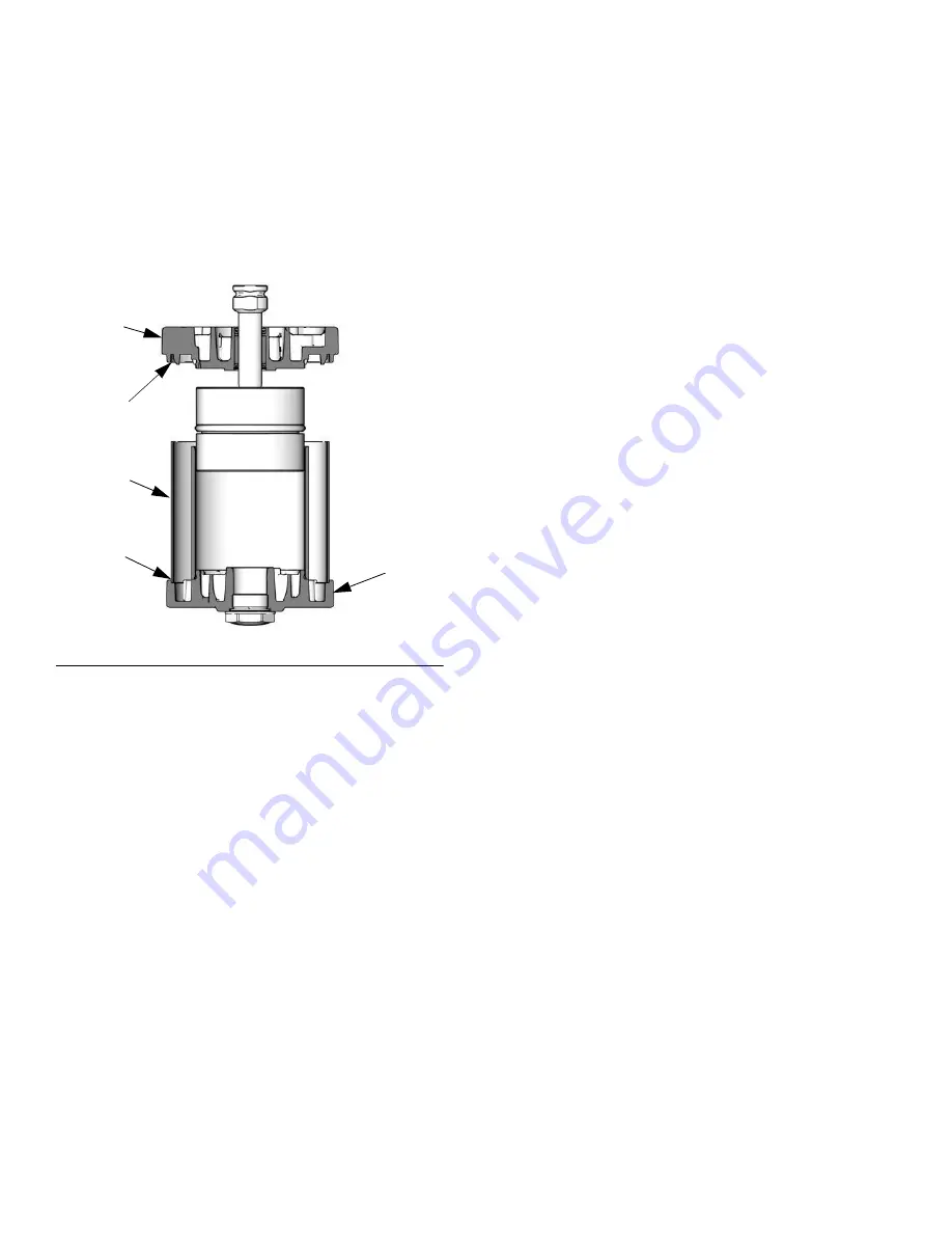
9. See F

IG

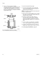
. 19. Carefully place the bottom 

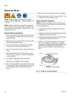
cover/piston assembly on the cylinder (205), sliding 

the piston (219) into the cylinder. The manifold 

surfaces of the top and bottom covers must align. 

Be sure the shield (206) is in the groove on both the 

top and bottom covers.

10. Install the tie bolts (212) hand tight.

11. Install two gaskets (208*) on the manifold (220). 

Install the manifold (220). Torque screws (211) to 

95-105 in-lb (10.7-11.9 N•m).

NOTE: 

The manifold is reversible for ease of placement 

of muffler or remote exhaust.

12. Align the air valve gasket (209*

†) on the manifold, 

then attach the air valve (214). Torque screws (211) 

to 95-105 in-lb (11-12 N•m).

13. Tighten the tie bolts (212) halfway. Work in a 

crisscross pattern. Check that the shield (206) 

remains in the grooves on both covers. Continue 

tightening the bolts in pattern to 11-13 ft-lb (15-18 

N•m).

14.

On 3.5 in. motors only,

 lubricate the o-ring (230*). 

Install it and the plug (231) in the top cover (210).

15. Lubricate and install pilot valves (213) in top and 

bottom cover. Torque to 95-105 in-lb (11-12 N•m).

16. See 

Reconnect the Air Motor

 on page 23.

F

IG

. 19. Align Shield in Grooves on Covers

groove

groove

201

206

ti16281a

210

Summary of Contents for Merkur ES

Page 1: ...l use only 15 1 Spray Packages 30 1 Spray Packages 100 psi 0 7 MPa 7 0 bar Maximum Air Inlet Pressure See page 3 for model information including maximum fluid working pressure Important Safety Instructions Read all warnings and instructions in this manual Save these instructions ti15590a ti15589a II 2 G Ex h T5 Gb X ...

Page 2: ...13 Wet Cup 13 Troubleshooting 14 Repair 16 General Information 16 To Remove Intake Valve Only 16 Disconnect the Displacement Pump 16 Disassemble the Pump 17 Reconnect the Displacement Pump 19 Repair Air Valve 19 Replace Pilot Valves 22 Disconnect the Air Motor 23 Reconnect the Air Motor 23 Repair Air Motor 24 Parts 27 Package Parts 27 Hose and Gun 32 Air Motor Parts 36 Air Valve Parts 38 Air Contr...

Page 3: ... 15 1 1500 10 3 103 Air assisted PerformAA 15 Stand Stainless Steel 24N548 A 30 1 3000 20 7 207 WB3000 Stainless Steel 24W281 B 15 1 1500 10 3 103 Air assisted PerformAA 15 Stand Plated Steel 24W283 B 15 1 1500 10 3 103 Air assisted PerformAA 15 Stand Stainless Steel 24W285 B 30 1 3000 20 7 207 Air assisted PerformAA 50 Stand Plated Steel 24W287 B 30 1 3000 20 7 207 Air assisted PerformAA 50 Stand...

Page 4: ...lectric lamps and plastic drop cloths potential static sparking Ground all equipment in the work area See Grounding instructions Never spray or flush solvent at high pressure Keep work area free of debris including solvent rags and gasoline Do not plug or unplug power cords or turn power or light switches on or off when flammable fumes are present Use only grounded hoses Hold gun firmly to side of...

Page 5: ...quipment manuals Read fluid and solvent manufacturer s warnings For complete information about your material request Safety Data Sheets SDSs from distributor or retailer Do not leave the work area while equipment is energized or under pressure Turn off all equipment and follow the Pressure Relief Procedure when equipment is not in use Check equipment daily Repair or replace worn or damaged parts i...

Page 6: ...d in approved containers and dispose of it according to applicable guidelines PERSONAL PROTECTIVE EQUIPMENT Wear appropriate protective equipment when in the work area to help prevent serious injury including eye injury hearing loss inhalation of toxic fumes and burns Protective equipment includes but is not limited to Protective eyewear and hearing protection Respirators protective clothing and g...

Page 7: ...ss to the valve The pump air regulator F controls pump speed and outlet pressure by adjusting the air pressure to the pump The air pressure relief valve P opens automatically to prevent overpressurization of the pump The gun air regulator E adjusts the air pressure to the air assisted spray gun The spray gun H dispenses the fluid The gun houses the spray tip not shown which is available in a wide ...

Page 8: ...th a maximum of 500 ft 150 m combined hose length to ensure grounding continuity Check electrical resistance of hoses If total resistance to ground exceeds 25 megohms replace hose immediately 3 Air compressor follow manufacturer s recommendations 4 Spray gun ground through connection to a properly grounded fluid hose and pump 5 Fluid supply container follow your local code 6 Object being sprayed f...

Page 9: ...the supplied hose clips qty of 7 Space clips as needed 6 Attach the fluid suction kit J to the pump inlet FIG 2 Typical Installation Air Assisted Stand Mount Package Shown A B C D F E G N J K L ti15591a H M P Key A Main Air Supply Line B Air Shutoff Valve C Air Filter D Bleed type Master Air Valve required E Gun Air Pressure Regulator F Pump Air Pressure Regulator G Gun Air Supply Line H Spray Gun...

Page 10: ...lowing the steps above if the spray tip or hose still seems completely clogged very slowly loosen the tip guard retaining nut or hose end coupling and relieve pressure gradually then loosen completely With tip removed trigger gun into waste container Trigger Lock See FIG 3 Always engage gun trigger lock when you stop spraying to prevent gun from being triggered accidentally by hand or if dropped o...

Page 11: ...9 in 0 483 mm Adjust the Atomization NOTE Use this procedure with airless and air assisted spray guns 1 Do not turn on atomizing air supply Fluid pressure is controlled by the air pressure supplied to the pump pump air regulator Set fluid pressure at low starting pressure For low viscosity fluids less than 25 sec 2 Zahn cup with lower percent solids typically less than 40 start at 300 psi 2 1 MPa ...

Page 12: ...y atomized and pulled into spray pattern Do not exceed 100 psi 0 7 MPa 7 bar air pressure to gun 3 See FIG 4 For narrower pattern turn pattern adjustment valve knob AA counterclockwise out If pattern is still not narrow enough increase air pressure to gun slightly or use different size tip Shutdown Follow Pressure Relief Procedure page 10 Always flush the pump before the fluid dries on the displac...

Page 13: ... fluid manufacturer or supplier for recommended flushing fluids and flushing frequency 1 Follow Pressure Relief Procedure page 10 2 Remove tip guard and spray tip from gun Refer to separate gun manual 3 Place suction tube in grounded metal pail containing cleaning fluid 4 Set pump to lowest possible fluid pressure and start pump 5 Hold a metal part of the gun firmly to a grounded metal pail 6 Trig...

Page 14: ...operating at high pressure or high cycle rate Reduce pressure cycle rate or duty cycle of motor Reduce dew point of compressed air in moisture coalescing filter Pump fails to operate Restricted line or inadequate air supply closed or clogged valves Clear line or increase air supply Check that the valves are open Obstructed fluid hose or gun fluid hose ID is too small Open clear use hose with large...

Page 15: ...r accelerated pump speed Exhausted fluid supply Refill and prime Held open or worn ball check valves or packings Clear valve replace packings See page 17 Fluid being pumped is visible in the packing nut wet cup Worn throat packings Tighten packing nut Replace throat packings See page 17 Bad spray pattern Clean or repair spray gun or tip See manual 3A8099 Problem Cause Solution ...

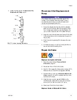
Page 16: ... hose 4 Remove the intake housing 110 See FIG 11 5 Clean or replace the ball guide 109 ball 116 seat 117 and o ring 111 6 Install the o ring 111 seat 117 intake ball 116 and ball guide 109 in the intake housing 110 7 Screw the intake housing 110 onto the cylinder 105 Torque to 70 80 ft lb 95 108 N m Disconnect the Displacement Pump 1 Stop the pump 2 Flush the pump if possible see page 13 Follow Pr...

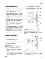
Page 17: ...t to drop the piston ball 120 Disassemble the piston packings from the piston 8 Clean and inspect all parts Replace any damaged parts Reassemble the Pump Assemble the Piston Rod 1 Hold the rod 119 upright in a vice 2 Place the piston ball 120 in the cavity of the rod 119 3 Install piston rod packings V packing models FIG 7 NOTE Soak the leather packings 113 125 in hydraulic oil for one hour before...

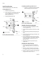
Page 18: ...102 onto the packing nut 103 4 Liberally lubricate the packings and the top 2 in 51 mm of the rod 119 5 Push the displacement rod 119 into the cylinder 105 from the bottom until the piston is completely in the cylinder and the rod protrudes from the packing nut 103 6 Grease the o ring 107 and install it on the cylinder 105 Assemble the Intake Housing 1 Install the o ring 111 seat 117 intake ball 1...

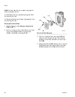
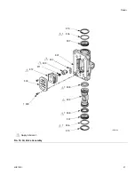
Page 19: ...alve Replace Complete Air Valve 1 Stop the pump Follow Pressure Relief Procedure page 10 2 Disconnect the air line to the motor 3 See FIG 18 on page 25 Remove four screws 211 Remove the air valve 214 and gasket 209 4 To repair the air valve go to Disassemble the Air Valve page 20 To install a replacement air valve continue with step 5 5 Align the new air valve gasket 209 on the manifold then attac...

Page 20: ...steps 1 3 under Replace Complete Air Valve page 19 2 See FIG 12 Use a 2 mm or 5 64 hex key to remove two screws 309 Remove the valve plate 305 cup 312 and spring 311 3 See FIG 13 Remove the snap ring 310 from each end Use the piston to push the end caps 307 out of the ends Remove end cap o rings 306 4 Remove the piston 302 Remove the u cup seals 308 from each end and the detent assembly 303 and de...

Page 21: ...Repair 3A0732U 21 FIG 13 Air Valve Assembly 1 Apply lubricant 310 307 307 309 305 312 311 303 302 308 308 301 304 310 ti16213a 306 306 1 1 1 1 1 1 1 1 ...

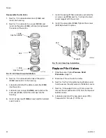
Page 22: ...ll the spring 311 Lubricate and install the air valve cup 312 see FIG 15 Align the small round magnet with the air inlet 8 Install the valve plate 305 Tighten the screws 309 to hold it in place Replace Pilot Valves 1 Stop the pump Follow Pressure Relief Procedure page 10 2 Disconnect the air line to the motor 3 See FIG 16 Push the safety spring 9 down and hold to access the pilot valve on the bott...

Page 23: ... tie rods are removed 9 Take the motor to a work bench See Repair Air Motor on page 24 Reconnect the Air Motor 1 Replace the motor on the mounting bracket 1 2 Screw the tie rods into the motor with the top hex nuts 17 attached Torque the tie rods to 5 10 ft lb 7 13 N m NOTE Always tighten the tie rods before tightening the top hex nuts 17 3 Tighten the top hex nuts 17 to secure the mounting bracke...

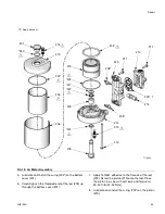
Page 24: ... 7 Remove the o ring 204 from the piston 8 Secure the piston 219 in a vise with soft jaws Use a wrench on the flats of the rod 218 to remove the rod and bottom cover assembly 201 from the piston 9 Remove the rod from the bottom cover assembly 10 Remove retaining ring 217 u cup seals 207 and o ring 202 from the bottom cover Reassemble the Air Motor NOTE For easier reassembly start with the top cove...

Page 25: ...hesive to the threads of the rod 218 Screw the piston 219 onto the rod Place the piston in a vise with soft jaws and torque to 35 40 ft lb 47 54 N m 8 Lubricate and install the o ring 204 on the piston 219 FIG 18 Air Motor Assembly TI16130a 201 215 214 213 211 202 203 204 219 209 208 207 205 206 210 212 220 202 208 211 213 217 218 207 230 231 1 1 1 1 1 1 1 1 Apply lubricant 1 1 ...

Page 26: ... of placement of muffler or remote exhaust 12 Align the air valve gasket 209 on the manifold then attach the air valve 214 Torque screws 211 to 95 105 in lb 11 12 N m 13 Tighten the tie bolts 212 halfway Work in a crisscross pattern Check that the shield 206 remains in the grooves on both covers Continue tightening the bolts in pattern to 11 13 ft lb 15 18 N m 14 On 3 5 in motors only lubricate th...

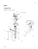
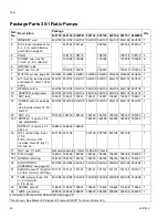
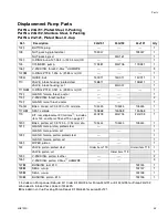
Page 27: ...3A0732U 27 Parts Package Parts TI16129a 1 23 13 16 21 11 42 19 17 18 9 8 7 10 15 20 37 38 22 26 Part of air motor 7 NOTE For hose and gun see page 32 12 2 3 4 5 6 Detail of Stand Kit 2 43 43 4 1 Ref TI16438a ...

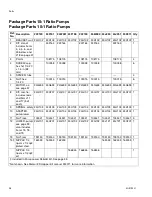
Page 28: ...3 1 8 KIT rod tie includes rods and items 11 and 17 3 of each 24G707 24G707 24G707 24G707 24G707 24G707 24G707 24G707 24G707 1 9 SPRING safety 24H103 24H103 24H103 24H103 24H103 24H103 24H103 24H103 24H103 1 10 ADAPTER pump lower 24H104 24H104 24H104 24H104 24H104 24H104 24H104 24H104 24H104 1 11 NUT lock 104541 104541 104541 104541 104541 104541 104541 104541 104541 3 12 LOWER pump see page 33 al...

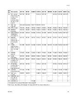
Page 29: ...008 24H008 24H008 24H008 24H008 24H008 24H008 24H008 24H008 1 23 SCREW ground 116343 116343 116343 116343 116343 116343 116343 116343 116343 1 26 WIRE grounding 238909 238909 238909 238909 238909 238909 238909 238909 238909 1 28 THROAT SEAL LIQUID 4 oz not shown 238049 238049 238049 238049 238049 238049 238049 238049 238049 1 37 STRAINER suction 3 8 in 10 mm OD tube pack of 3 24F160 24F160 24F160 ...

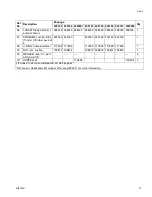
Page 30: ...d 19 24G702 24G702 24G702 24G701 24G701 24G701 24G701 24G701 1 13 NUT jam 195150 195150 195150 195150 195150 195150 195150 195150 1 15 NIPPLE 1 4 npsm x 1 4 npt plated steel 162453 162453 162453 162453 162453 1 NIPPLE 1 4 npsm x 1 4 npt sst 166846 166846 166846 1 16 KIT suction hose 5 gal 19 l 3 8 in 10 mm OD includes items 37 qty 1 38 and 42 24F148 24F148 24F148 24F148 24F148 24F148 1 17 NUT hex ...

Page 31: ... 38 O RING fluoroelastomer 117559 117559 117559 117559 117559 117559 1 42 NUT jam suction 15E813 15E813 15E813 15E813 15E813 15E813 1 43 WASHER lock 1 4 part of stand kit 2 6 44 HOPPER kit 17A493 17A493 1 Ref No Description Package Qty 24F152 24F153 24W287 24F154 24F155 24F156 24F157 24W285 Included in Pump Lower Rebuild Kit See page 42 Not shown See Merkur ES Hopper Kit manual 334011 for more inf...

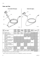
Page 32: ...N air assisted PerformAA 50 see manual 3A8099 26B510 26B510 1 GUN airless PerformAA 50 Airless see manual 3A8099 26B520 1 32 HOSE fluid 1 8 in 3 mm ID nylon 1 4 npsm f plated steel couplings 25 ft 7 6 m 24F165 24F165 24F165 24F165 1 HOSE fluid 1 8 in 3 mm ID nylon 1 4 npsm f sst couplings 25 ft 7 6 m 24F166 24F166 1 33 CLIP hose pack of 7 24H005 24H005 24H005 24H005 24H005 7 36 TIP spray tip AXF41...

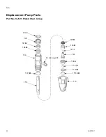
Page 33: ...3 Displacement Pump Parts Part No 24G701 Plated Steel V Packing Part No 24G702 Stainless Steel V Packing ti32016a 119 125 117 116 110 113 123 102 106 103 112 107 111 109 122 121 120 114 105 124 104 126 15 see page 28 ...

Page 34: ...Parts 34 3A0732U Displacement Pump Parts Part No 24J121 Plated Steel U Cup 119 117 116 110 102 103 130 107 111 109 120 105 124 129 15 see page 28 127 128 ...

Page 35: ...l 1 116 BALL intake sst 0 500 in 13 mm dia 105445 105445 105445 1 117 SEAT carbide 15A968 15A968 15A968 1 119 KIT rod displacement Chromex includes item 124 and items 18 and 19 on page 27 24G703 24G704 24G703 1 120 BALL piston sst 0 3125 in 7 94 mm dia 105444 105444 105444 1 121 GLAND male piston plated steel 1 GLAND male piston sst 1 122 GLAND female piston plated steel 1 GLAND female piston sst ...

Page 36: ... 36 3A0732U Air Motor Parts Part No 24G693 2 5 in 63 5 mm Part No 24G694 3 5 in 88 9 mm shown TI16130a 201 215 214 213 211 202 203 204 219 209 208 207 205 206 210 212 220 202 208 211 213 217 218 207 230 231 ...

Page 37: ... Manifold Assembly 220 this table 2 209 GASKET air valve Not sold separately See Air Motor Seal Kit Valve Repair Kit 24A537 Valve Seal Kit 24A535 below or Manifold Assembly 220 this table 1 210 KIT cover top includes 202 and 213 qty 1 of each 15X353 also includes 230 and 231 24H004 15X353 1 211 SCREW M6 x 25 Not sold separately See Manifold Assembly 220 this table or Air Valve Replacement Kit page...

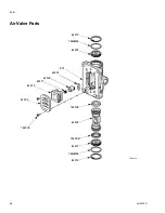
Page 38: ...Parts 38 3A0732U Air Valve Parts 310 307 307 309 305 312 311 303 302 308 308 301 304 310 ti16213a 306 306 ...

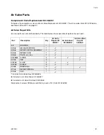
Page 39: ...kit options for each part Ref Description Qty Air Valve Repair Kit 24A537 Air Valve Seal Kit 24A535 Air Valve End Cap Kit 24A360 301 HOUSING 1 302 AIR VALVE PISTON 1 303 DETENT PISTON ASSEMBLY 1 304 DETENT CAM 1 305 PLATE air valve 1 306 O RING 2 307 CAP 2 308 U CUP 2 309 SCREW 2 310 SNAP RING 2 311 DETENT SPRING 1 312 CUP 1 Included in Air Valve Seal Kit 24A535 Included in Air Valve Repair Kit 24...

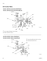
Page 40: ...ttings Used on stand mount units only 1 2 1 Part No 24H162 Air Assisted Wall Mount Part No 24H163 Air Assisted Stand Mount Part No 24H164 Airless Wall Mount Part No 24H165 Airless Stand Mount TI16229a 420 402 405 404 407 409 410 411 412 413 1 1 Connect tubing 406 between these two fittings Used on stand mount units only 1 2 401 418 418 418 2 2 2 421 422 422 ...

Page 41: ...9 1 406 TUBE polyurethane 3 8 in 10 mm OD tube 2 ft 0 61 m 24H008 24H008 24H008 24H008 1 407 VALVE ball air 3 8 npt fbe 114362 114362 114362 114362 1 408 NIPPLE 1 4 npsm x 1 4 npt 162453 162453 1 409 ELBOW swivel 3 8 npt m x 3 8 in 10 mm OD tube 16F151 16F151 16F151 16F151 1 410 ELBOW 1 4 npt f x 1 8 npt m 121150 121150 121150 121150 1 411 VALVE safety relief 110 psi 113498 113498 113498 113498 1 ...

Page 42: ... 5 gal 19 l 5 8 in 16 mm OD 24F149 Suction Tube 1 gal 3 8 l 11 32 in 9 mm OD 24F147 Standard Push on Strainer Kit 24F160 Screw on Strainer Kit for 24F149 5 8 in Suction Hose Kit 256426 Air Gauge Lens Cover Kit sheet of 12 covers 193199 Throat Seal Liquid TSL 4 oz 118 ml 238049 Throat Seal Liquid TSL 8 oz 236 ml 206994 Alternate U Cup Pump Packing Kit UHMWPE 24H665 Hopper Kit 17A493 Hopper Screens ...

Page 43: ...U 43 Package Dimensions Package A inch mm B inch mm C inch mm D inch mm Wall Mount 20 2 513 Stand Mount 29 0 737 17 4 442 18 4 467 Stand Mount with Hopper 29 0 737 17 4 442 26 5 673 ti16287a A B ti16288a C D Front View Top View ...

Page 44: ...less stand 25 11 24F156 30 1 plated steel AA wall 23 10 24F157 30 1 plated steel AA stand 26 12 24F158 15 1 stainless steel AA wall 20 9 24F159 15 1 stainless steel AA stand 23 10 24W281 15 1 plated steel AA stand hopper 32 15 24W283 15 1 stainless steel AA stand hopper 32 15 24W285 30 1 plated steel AA stand hopper 35 16 24W287 30 1 stainless steel AA stand hopper 35 16 24X311 15 1 plated steel A...

Page 45: ...ll Bracket Mounting Hole Diagram 2 x 0 281 9 32 in 7 mm For wall mount only TI16289a 4 40 in 112 mm 2 x 0 312 5 16 in 8 mm For wall mount or to attach stand to bracket 5 10 in 130 mm 2 69 in 68 mm 2 x 0 48 in 12 mm 2 x 0 62 in 16 mm 2 x 0 35 in 9 mm ...

Page 46: ... Sound pressure 76 5 24G694 Air Motor Sound pressure 77 9 dBA Sound power 84 5 dBA Wetted parts Plated steel pumps with v packings Stainless steel nickel plated carbon steel tungsten carbide ptfe acetal leather ultra high molecular weight polyethylene Stainless steel pumps with v packings Stainless steel tungsten carbide ptfe acetal leather ultra high molecular weight polyethylene Plated steel pum...

Page 47: ... C 30 60 90 120 150 180 210 Cycles per Minute Air Flow scfm m 3 min Fluid Outlet Pressure psi MPa bar Fluid Flow gpm lpm tested in No 10 weight oil KEY 240 10 5 0 3 1400 10 100 0 05 0 2 9 0 0 25 7 5 0 2 6 0 0 17 4 5 0 13 3 0 0 08 1 5 0 04 0 15 0 6 0 10 0 4 0 20 0 75 0 25 0 9 0 30 1 1 0 35 1 3 0 40 1 5 1200 8 80 1000 7 70 800 5 5 55 600 4 40 400 3 30 200 1 4 14 0 0 ...

Page 48: ...les per Minute Air Flow scfm m 3 min Fluid Outlet Pressure psi MPa bar Fluid Flow gpm lpm tested in No 10 weight oil KEY 30 60 90 120 150 180 210 240 0 05 0 2 0 15 0 6 0 10 0 4 0 20 0 75 0 25 0 9 0 30 1 1 0 35 1 3 0 40 1 5 0 18 0 0 5 3000 21 210 9 0 0 25 15 0 42 12 0 0 34 6 0 0 17 3 0 0 08 2500 17 5 175 2000 14 140 1500 10 5 105 1000 7 70 500 3 5 35 0 ...

Page 49: ...California Proposition 65 3A0732U 49 California Proposition 65 CALIFORNIA RESIDENTS WARNING Cancer and reproductive harm www P65warnings ca gov ...

Page 50: ... material or workmanship repairs will be made at a reasonable charge which charges may include the costs of parts labor and transportation THIS WARRANTY IS EXCLUSIVE AND IS IN LIEU OF ANY OTHER WARRANTIES EXPRESS OR IMPLIED INCLUDING BUT NOT LIMITED TO WARRANTY OF MERCHANTABILITY OR WARRANTY OF FITNESS FOR A PARTICULAR PURPOSE Graco s sole obligation and buyer s sole remedy for any breach of warra...

Reviews: