This manual contains IMPORTANT
WARNINGS AND INSTRUCTIONS
READ AND RETAIN FOR REFERENCE
Rev. D
Supersedes C
308–055
PRO 3500SC
Electrostatic Spray Gun
FLUID SUPPLY HOSE CONVERSION KIT
Kit Part No. 223–780
For PRO 3500SC Electrostatic Spray Gun, part no.
222–300. See instruction manual 307–912 for complete
gun instructions and safety warnings.
This kit is designed to maintain a proper electrostatic field
when spraying conductive solvent-based fluids with a
resistivity range of 2.0 megohm cm to infinity, measured
with a Graco Paint Resistance Meter. See
ACCESSORIES to order the meter.
WARNING
To avoid static sparking, which could result in fire or
explosion and serious bodily injury or property
damage, DO NOT use this kit with fluids having a
resistivity less than 2.0 megohm cm.
ALWAYS ground the fluid source by using a ground
wire and clamp. NEVER electrically isolate the fluid
source.
NOTE:This kit has not been tested by the Canadian Standards
Association. Installing this kit to certified or approved
electrostatic systems voids previous C.S.A. certifica-
tion.
INSTALLATION
WARNING
Installing, operating, and servicing this equipment
requires access to parts which may cause electric
shock or other serious bodily injury if work is not
performed properly. Read and follow all safety
warnings in instruction manual 307–912. Do not
install, operate, or service this equipment
unless you are trained and qualified.
BEFORE servicing the fluid nozzle or spray gun,
and before disassembling the gun, always turn
the ES ON-OFF valve lever to OFF, turn off the air
and fluid supply to the gun, and trigger the gun to
relieve the fluid pressure.
BE SURE your installation complies with National,
State, and Local codes for the installation of elec-
trical apparatus in a Class 1, Group D, Divisions 1
and 2 Hazardous Location.
PRO 3500SC Gun Disassembly
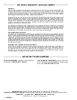
1.
Remove the fluid tube fitting (B) and fluid seal (A)
from the gun. See Fig 1.
2.
Remove the air fitting (D), exhaust tube clamp (F),
and the exhaust tube (E).
Keep these parts for
reassembly.
Fig 1
A
B
KEY
A
Fluid Seal
B
Fluid Tube Fitting
C
Gun Fitting Bracket
D
Air Fitting
E
Exhaust Tube
F
Exhaust Tube Clamp
G
Fluid Tube Nut
H
Ferrules
E
F
D
C
G
H
3.
Remove the gun fitting bracket (C) with the hose
assembly.
GRACO INC. P.O. BOX 1441 MINNEAPOLIS, MN 55440–1441
COPYRIGHT 1990, GRACO INC.


