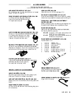
ISOLATION STAND PARTS DRAWING AND LIST
401
402
403,407
404
405
406
Part No. 223–445
Isolation Stand Assembly
For 15 gallon (57 liter) fluid container
409
REF
NO.
PART NO. DESCRIPTION
QTY
401
185–468
STAND, bare
1
402
185–946
GRATE. grounding
1
403
110–629
CLAMP, cable
1
404
110–757
U-BOLT, clip
1
405
223–539
CABLE ASSEMBLY, 36” (914 mm)
(from terminal block to
fluid supply unit)
1
406
223–529
CABLE ASSEMBLY, 12” (305 mm)
(from terminal block to
voltage control)
1
407
105–967
SCREW, thread forming, pnh;
10–16 x 0.5 in.
1
409
100–077
NUT, hex; 5/16–18
2
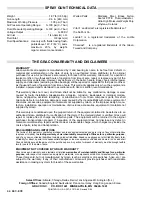
GUN CONVERSION KIT PARTS DRAWING AND LIST
28
Part No. 223–114
Gun Conversion Kit
REF
NO.
PART NO. DESCRIPTION
QTY
8
223–653
NUT, air cap retaining
1
20
186–615
ELECTRODE
1
28
223–444
ROD, packing assembly
1
71
186–118
SIGN, warning
(not shown)
1
The Kit Ref Nos. correspond with the Gun Ref Nos. on
page 37.
8
20
Manual Change Summary
The following parts have been changed in this revison.
Assembly
Changed
Part
Status
Ref
No.
Part No.
Name
222–700
Spray Gun
Old
New
45
45
185–117
188–486
Cap, air valve
Cap, air valve
Air Line Ac-
cessories
Old
New
–
–
110–805
112–534
Disconnect
Disconnect/
Swivel
Other changes were made on the following pages.
Page 28: A NOTE was added under Turbine Alternator
Replacement to replace turbine bearings after 2,000
hours of operation.
Page 44: Under WARRANTY, the barrel, handle, trigger,
and hook were added as parts that will be repaired or re-
placed for thirty-six months or six thousand hours of op-
eration from time of sale.
Summary of Contents for PRO 3500WB
Page 11: ... NOTES ...
Page 35: ... NOTES ...


