308496 13
Installation
Optional Fiber Optic Cable Connection
WARNING
ELECTRIC SHOCK HAZARD
To reduce the risk of an electric shock,
do not use the Graco ES Display Module
readings to determine if your system is
discharged. The display modules will only display
the system voltage while the guns power supply
is operating. Follow the Fluid Voltage Discharge
and Grounding Procedure, page 19, to ensure
the system is discharged.
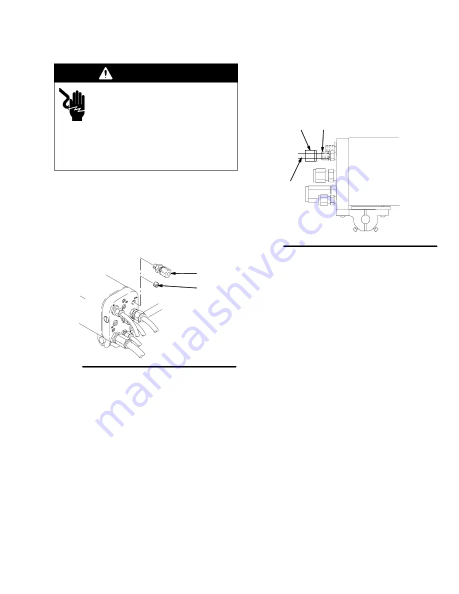
An optional fiber optic fitting (124) is shipped unas-
sembled with the gun. If an ES (kV) display module is
used, install the fitting in the manifold. See Fig. 3, page
10, for a schematic of the fiber optic connections.
1.
Remove the 1/8 npt plug (115) from the manifold’s
fiber optic port, and install the black fiber optic
fitting (124). See Fig. 8.
Fig. 8
115
124
04305
2.
Remove the nut (EE) from the fiber optic fitting
(124), and slide the nut over the end of the fiber
optic cable (FF). See Fig. 9.
3.
Insert the cable (FF) into the fitting (124), and push
the cable in until it bottoms out. Tighten the nut
(EE) to secure the cable.
Fig. 9
EE
FF
04306
124
4.
If you have two bulkhead splices in your system, it
is recommended that you install the fiber optic lens
kit, as described on page 14.
NOTE: Most of the fiber optic light transmission loss
occurs at the bulkhead splices. For the strongest light
signals, use a minimum number of bulkhead splices. A
maximum of two splices, with a total of 108 feet (32.94
m) of cable, is recommended.
5.
See manual 308265 to install a Graco ES Display
Module.
Summary of Contents for PRO 5500wb
Page 49: ...308496 49 Notes ...
Page 59: ...308496 59 Notes ...


