


308496 45
Service
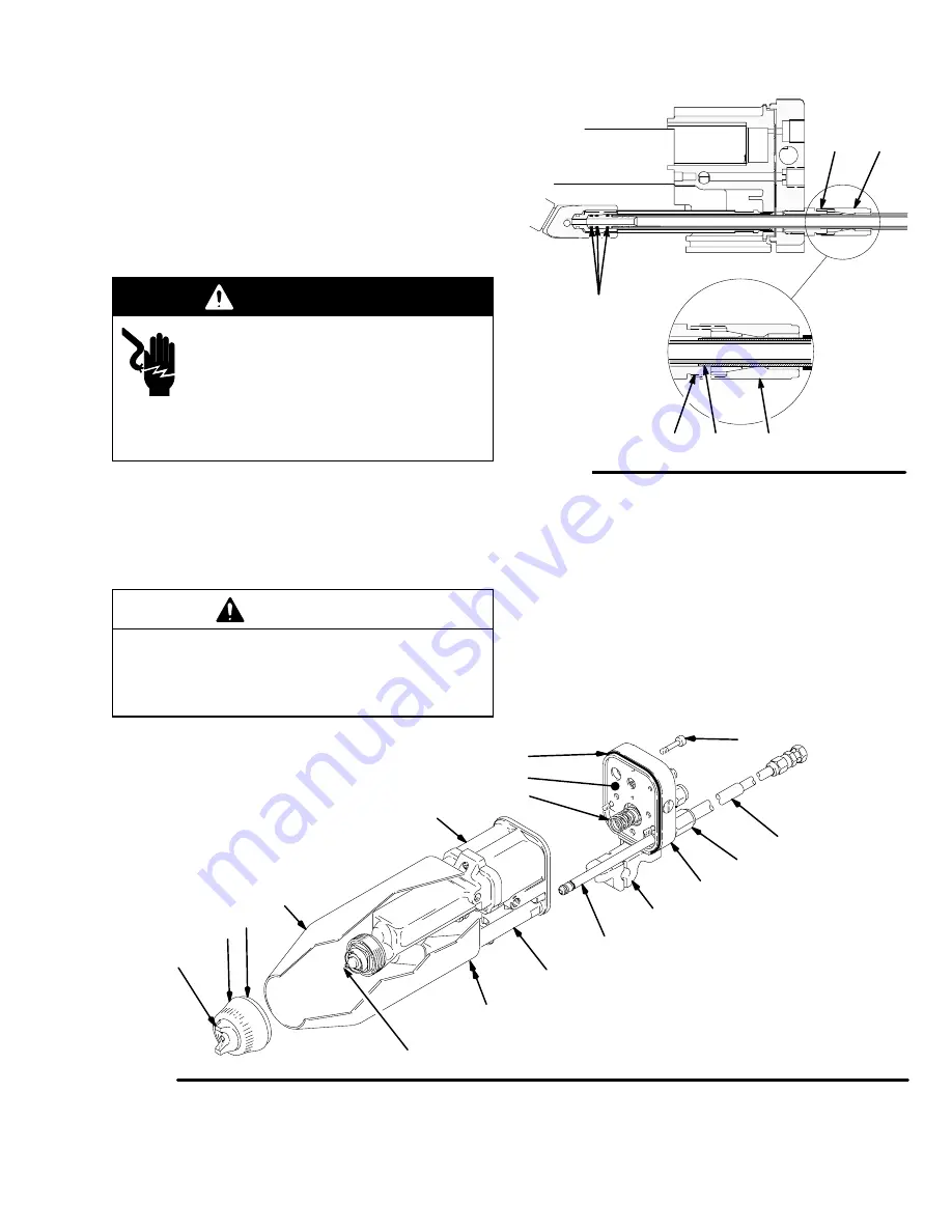
Install the Gun onto the Manifold
(continued)
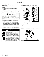
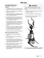
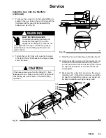
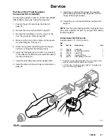
7.
To ensure the o-rings (C) on the barbed-fitting are
seated in the gun, loosen the nut (D) and push the
fluid hose into the gun until the barbed-fitting
bottoms out. See Fig. 40.
WARNING
ELECTRIC SHOCK HAZARD
To maintain grounding continuity, the
conductive hose layer (E) must be
engaged in the fitting (P1) when the nut
(D) is tightened. See Fig. 40. Failure to properly
install the hose into the fitting could result in an
electric shock.
8.
Tighten the nut (D) firmly with a wrench to about
55 in-lb (6.2 N
m). Pull back on the hose to make
sure it is secure.
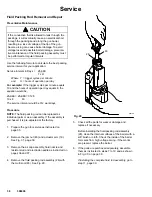
CAUTION
If the hose comes loose from the fitting (P1), fluid
leakage will occur. Make sure the nut (D) is tight and
that nothing will pull or catch on the hose during
operation.
ÇÇÇÇÇ
ÇÇÇÇÇ
Fig. 40
P1
C
D
E
D
P1
05927
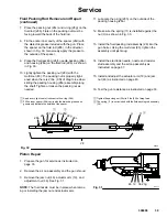
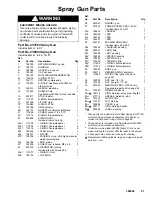
9.
Slide the shroud (2) onto the gun (B). See Fig. 41.
10. Carefully install the air cap (12) and gasket (3–not
shown). Do not bend the electrode (13), and be
sure to insert the electrode wire through the center
air cap hole. Rotate the air cap horns to the de-
sired position.
11. Make sure the o-ring (9) is in place on the air cap
retaining nut (1). Tighten the retaining nut until the
air cap (12) is held firmly in place; you should not
be able to rotate the air cap horns by hand.
Fig. 41
101
106
102
21
2
121
108
105
04321
B
1
9
12
13
17
A
D
E
Summary of Contents for PRO 5500wb
Page 49: ...308496 49 Notes ...
Page 59: ...308496 59 Notes ...


