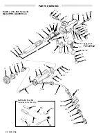
background image

12 307-706

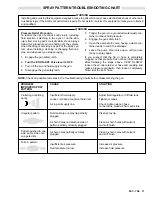
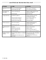
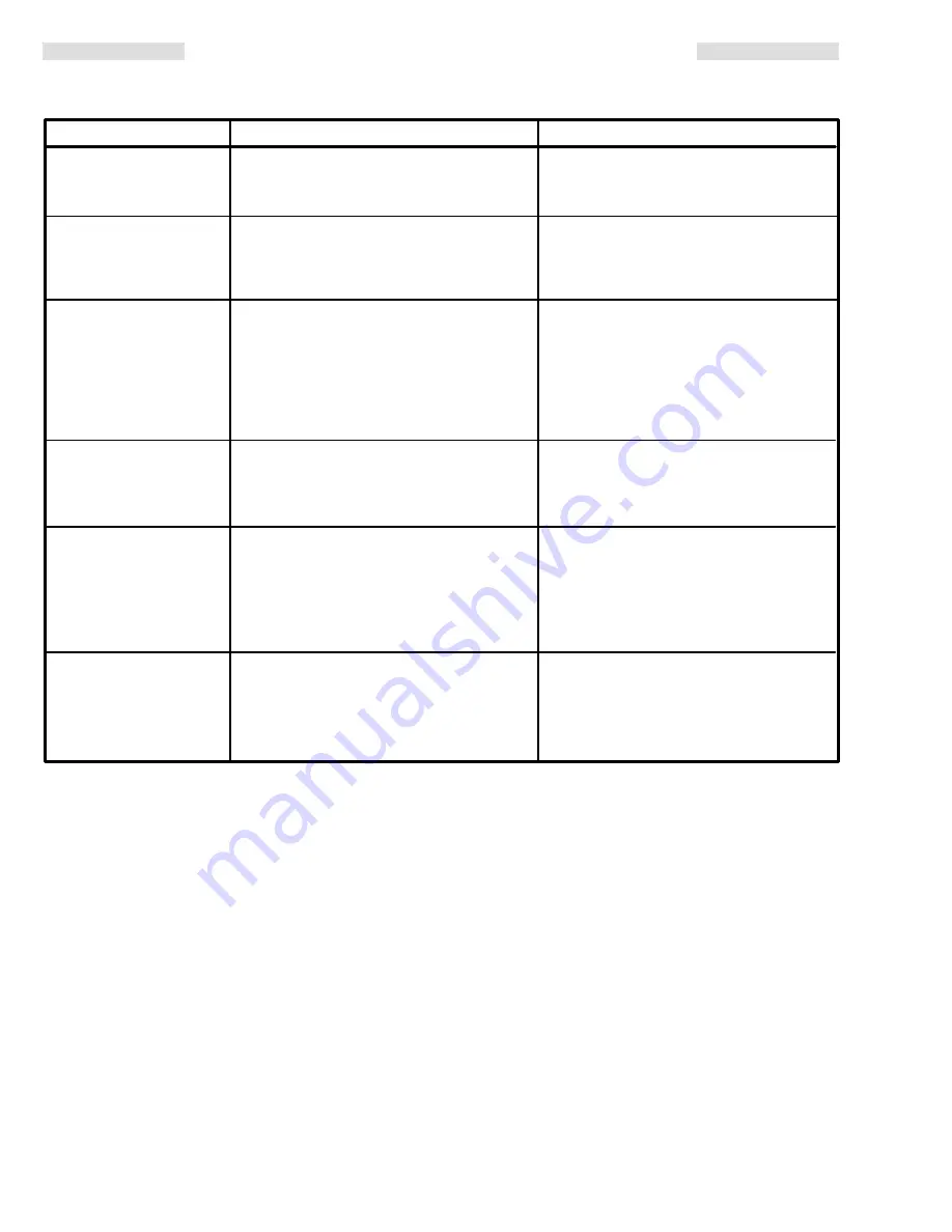
GUN OPERATION TROUBLESHOOTING CHART

PROBLEM

CAUSE

SOLUTION

Air leakage from front of
gun.

Fluid leakage from 
front of gun.

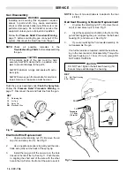
Air valve not seating properly.

Clean, service. See page 21.

Air stem packing too tight.

Loosen packing. See page 21.

Too much air pressure.

Reduce,use least air pressure 
needed for good results.

Fluid thinned too much.

Properly thin fluid.

Excessive spray fog.

Loose or worn fluid seat.

Tighten or replace fluid seat and/or  
electrode. See page 16.

Loose spray tip. 

Tighten spray tip.

Insufficient air pressure.

Increase, use least air pressure 
needed for good results.

Using too large of a spray tip.

Use a smaller size spray tip.

Fluid poorly mixed or filtered.

Remix or refilter fluid.

Improper thinner being used.

Use proper thinner.

“Orange Peel” finish.

No fluid sprays from 
gun.

Fluid low.

Check, add if necessary.

Broken fluid needle shaft.

Replace needle.

Dirty or clogged spray tip.

Clean spray tip. See page 10.

Damaged spray tip.

Check, replace spray tip. See page 9.

Exhaust air flow insufficient or not directed  Check for proper CFM, check baffles,  
properly.

and direction of air flow.

Improper distance between gun and 

Adjust distance to 203–305 mm 

work piece.

(8–12 in.).

Equipment covered  
with fluid.

Summary of Contents for PRO AA4000

Page 1: ...2 061 4 497 447 4 554 622 U K Patent No 2 140 327B 2 111 406B 2 142 559B 2 147 158 Patented 1986 1987 Canada Brevete 1986 1987 French Patent No 82 21202 84 07942 84 10234 Italian Patent No 1 111 380 West German Patent No DE 22 09 896 Model PRO AA4000 MANUAL MID RANGE ELECTROSTATIC AIR ASSISTED AIRLESS SPRAY GUN 66 bar 950 psi MAXIMUM WORKING FLUID PRESSURE 7 bar 100 psi MAXIMUM WORKING AIR PRESSUR...

Page 2: ... ...

Page 3: ...on of equipment NOTE Identifies essential procedures or helpful information FLUID INJECTION INJURY A serious injury which may ap pear to be a simple cut caused by high pressure injection of fluid directly into the body PRESSURE RELIEF PROCEDURE A safety procedure for relieving air and fluid pressure in the system FOR YOUR SAFETY Alerts user to read the additional safety warnings on the page indica...

Page 4: ...on Safety Latch shown in open or Spray position SPRAY LOCK SPRAY LOCK Diffuser The gun diffuser which is part of the ball seat housing breaks up spray and reduces the risk of fluid injection when the spray tip is not installed To check diffuser operation follow the Pressure Relief Procedure below then remove the spray tip Aim the gun into a grounded metal pail With the turbine air OFF and using th...

Page 5: ...ive objects or devices in the spray area including paint containers and wash cans must be properly grounded 6 All persons entering the spray area shoes must have conductive soles such as leather or personal grounding straps must be worn Rubber or plastic soles are not conductive The operator must not wear gloves which insulate the hand from spray gun The gloves must be conductive or modified as sh...

Page 6: ...sign The particular type and size system for your operation must be custom designed for your needs For assistance in designing a system contact your Graco representative The pump you use should have a maximum working pressure of 66 bar 950 psi If the pump you are using has a higher maximum working pressure a regulator MUST be used to limit the pressure to 66 bar 950 psi Graco s 10 1 Ratio Monark P...

Page 7: ...o the pump Install an additional bleed type valve on each pump air supply line to relieve air trapped between this valve and the pump after air regulator is shut off WARNING The bleed type air shutoff valve is required in your system to relieve air trapped between this valve and the pump after the air regulator is closed Trapped air can cause the pump to cycle unex pectedly which could result in s...

Page 8: ...scharged When you release the trigger the fluid stops before the air flow stops This helps prevent fluid buildup on the air cap When spraying the ES indicator lights 44 should glow indicating the electrostatic charge See Fig 5 CAUTION Be careful not to damage the electrode by jam ming it into an object when operating or setting down the gun Operating Checklist Check the following list daily before...

Page 9: ...ectrostatics on yet 1 Set the fluid pressure at about 21 bar 300 psi using the fluid regulator 2 Trigger the gun to check the atomization don t be concerned about the pattern shape yet 3 Increase the fluid pressure just to the point that any further increase in fluid pressure does not signifi cantly improve fluid atomization DO NOT exceed 66 bar 950 psi fluid pressure 4 Be sure the fan adjusting k...

Page 10: ...ey are damaged a Remove the air cap and spray tip b Clean the tip and air cap with solvent and scrub with a soft brush WARNING To avoid damaging the ball seat housing resistor use a soft bristle brush dipped in solvent to clean DO NOT soak it in solvent A damaged resistor will impair the electrical continuity and could result in electrical discharge which could cause serious injury fire or explosi...

Page 11: ... to catch the drainage 8 Leave the pump drain valve open until you are ready to spray again If you suspect that the tip or hose is completely clogged or that pressure has not been fully relieved after following the steps above VERY SLOWLY loosen the air cap retainer or hose end coupling and relieve pressure gradually then loosen completely Now clear the tip or hose NOTE Check all possible remedies...

Page 12: ...p Insufficient air pressure Increase use least air pressure needed for good results Using too large of a spray tip Use a smaller size spray tip Fluid poorly mixed or filtered Remix or refilter fluid Improper thinner being used Use proper thinner Orange Peel finish No fluid sprays from gun Fluid low Check add if necessary Broken fluid needle shaft Replace needle Dirty or clogged spray tip Clean spr...

Page 13: ...ance Check power supply resistance See page14 Damaged electrode wire Replace electrode wire See page 16 Faulty turbine alternator Be sure plug is in place on back of turbine alternator housing Remove and test turbine alternator See page 20 Poor wrap around Operator gets mild shock Operator not properly grounded Be sure floor is properly grounded or is in contact with ungrounded Wear shoes with con...

Page 14: ... sistance should be between 115 152 megohms If the re sistance is outside the specified range go to the next test If the resistance is correct refer to the Electrical Troubleshooting Chart on page 13 for other possible causes of poor performance Test Power Supply Resistance Remove the power cartridge 1 from the gun handle 32 See Power Cartridge Replacement Remove the turbine alternator 1a from the...

Page 15: ...asure the resistance between the conductive rod JJ and the resistor LL in the outside diameter of ball seat housing 14 See Fig 10 The resistance should be 20 30 megohms If the resis tance is correct the electrode wire is defective and must be replaced See Electrode Wire Replacement If the resistance is outside the specified range the resistor is defective and the ball seat housing 14 must be repla...

Page 16: ... 13 Spray Tip GG Electrode Wire GG 11 12 13 Electrode Wire Replacement 1 Unscrew the retaining nut 11 Remove the air cap 12 and spray tip 13 See Fig 11 2 Use a needle nose pliers to gently pull the elec trode wire GG out the back of the spray tip 3 Install the long end of the new wire in the hole closest to the tab of the tip See Fig 11 Push the wire in aligning the short end of the wire with the ...

Page 17: ...emoved reinstall it as described on page 18 2 Be sure the gasket 4 is in place Replace if damaged Place the barrel over the power cartridge 1 and onto the gun handle 32 See Fig 14 3 Install the two socket head cap screws 45 and tighten with the wrench 63f supplied See Fig 13 Snap the ES indicator lights in place over the socket head cap screws 4 Insert the fluid tube 20 into the fluid inlet of the...

Page 18: ...sembly 17a Adjustment Nut 21 Nut 63f Wrench 21 17a 17 63f Fig 17 KEY 17a Adjustment Nut 21 Nut 63c Pressing Tool 21 17a 63c Bottom of thread Check the Gun Safety Latch WARNING Check to be sure the gun safety latch works prop erly each time after you change the needle Safety latch failure or improper use of the safety latch can result in accidental gun triggering which could cause fluid injection o...

Page 19: ... the power cartridge Inspect the power cartridge cavity in the handle for dirt or moisture Clean out the cavity with a clean dry rag if necessary Moisture and other contaminants may damage electronic circuitry All the o rings 1b 3a 3c and the compression spring 3b must be in place or the gun will malfunction NOTE The cushion 9b is part of the gun barrel and should never be removed If it ever is re...

Page 20: ...om this value replace the alternator 4 Measure the resistance between each outer ter minal of the 3 wire connector NN and the turbine alternator housing 1a The resistance should be in finite If the resistance is not infinite replace the alternator 5 Partially connect the 3 wire connector NN onto the prongs inside the power supply 3 See Fig 21 Using a small screwdriver push the connector onto the p...

Page 21: ...sting screw 48 back the adjusting screw out of the valve housing 47 until it bottoms out against the retaining ring 9 Apply PTFE paste to the threads of the valve housing 47 and install it in the handle 32 Torque the housing to 1 1 1 4 N m 10 12 in lb Air Valve Replacement 1 Using a screwdriver remove the retainer 57 spring 55 and air valve 54 See Fig 23 2 Remove the trigger by removing the screws...

Page 22: ...y aligned with the bracket 28 then remove the bracket and bulk head retainer 75 from the gun handle 4 Pull the muffler 33 from the gun handle and replace with a new muffler 5 Insert a 3 18 mm 0 125 in rod into one of the holes in the valve check retainer 29 and pry it out of the bracket 28 Be ready to catch the ball 31 and spring 30 as the valve check retainer 29 is removed 6 Install a new ball 31...

Page 23: ...STRICTOR 2 101 107 414 SPRING compression 2 102 100 172 BALL 3 16 diameter 2 Low Air Flow Restrictor Kit 223 830 Includes Ref No Part No Description Qty 100 180 763 RESTRICTOR 2 101 107 414 SPRING compression 2 102 100 172 BALL 3 16 diameter 2 MUST also order Air Cap 220 535 100 101 102 Optional Air Cap 220 535 MUST be used with Low Air Flow Restrictor Kit 223 830 at left Must order separately Spr...

Page 24: ...3g 37 2 37 32 34 55 57 56 54 50 51 49 46 48 47 39 40 3c 1a 43 42 41 1b 52 53 19 76 77 29 30 31 REF 28 33 32a Apply Loctite 801 21 Torque to 3 4 N m 25 in lb 11 12 13 13a 14 17 20a 20 20a REF 32 28 75 24 26 25 22 44 45 REF 17 17a 21 9 5 4 Part No 218 668 Series B Model PRO AA4000 Gun 1 9a 9b ...

Page 25: ...SCRIPTION QTY 34 104 765 PLUG pipe hdls 1 8 27 npt 1 37 103 648 O RING Viton 2 38 181 326 VALVE air 1 39 105 681 RING retaining external 1 40 181 383 SEAL valve acetal 1 41 100 172 BALL 3 16 dia 2 42 107 414 SPRING compression 2 43 179 994 RESTRICTOR 2 44 218 179 LIGHT indicator ES 2 45 107 100 SCREW cap socket hd M5 x 0 8 x 12 2 46 103 557 O RING Viton 1 47 180 713 HOUSING valve 1 48 180 714 SCRE...

Page 26: ...H Color coded red Stainless steel braid ground path Part No Length 235 068 1 8 m 6 ft 235 069 5 m 15 ft 235 070 8 m 25 ft 235 071 11 m 36 ft 235 072 15 m 50 ft 235 073 23 m 75 ft 235 074 30 5 m 100 ft Quick Disconnect Coupling Assy 110 806 FM Approved Includes a quick disconnect coupling insert which replaces air inlet fitting 179 400 and a shut off coupling body left hand thread which connects to...

Page 27: ...id Filters 207 bar 3000 psi MAXIMUM WORKING PRESSURE Part No Description 214 570 With aluminum bowl and support 218 029 With carbon steel bowl and support Stainless Steel Screens Part No Description 167 024 595 micron 30 mesh 167 025 250 micron 60 mesh 167 026 149 micron 100 mesh 167 027 74 micron 200 mesh High Pressure Ball Valves 350 bar 5000 psi MAXIMUM WORKING PRESSURE Install in outlets for i...

Page 28: ...for use in Hazardous areas Gun Cover 218 374 Package of 10 disposable gun covers Electrode Wires 218 751 Box of 10 replacement electrode wires for spray tip Compression Spring 105 673 For increased shut off force when spraying plural component materials 105 673 Grounding Clamp And Wire 222 011 12 ga 25 ft 7 6 m wire Warning Signs FM Approved Available from Graco at no extra charge Must be ordered ...

Page 29: ...ntify the distributor closest to you 1 800 328 0211 Toll Free FOR TECHNICAL ASSISTANCE service repair infor mation or assistance regarding the application of Graco equipment 1 800 543 0339 Toll Free AIR FLOW CHART 0 2 4 6 8 10 12 14 16 0 10 20 30 40 50 60 70 80 AIR CONSUMPTION SCFM AIR FLOW WITH THE FAN ADJUSTMENT SET FOR THE WIDEST PATTERN AND THE TURBINE ON GUN INLET PRESSURE PSI AIR CAP 223 167...

Page 30: ... 250 8 10 219 211 100 150 4 6 0 279 0 011 300 10 1 219 311 150 200 6 8 219 411 200 250 8 10 219 511 250 300 10 12 219 611 300 350 12 14 219 213 100 150 4 6 0 330 0 013 400 13 5 219 313 150 200 6 8 219 413 200 250 8 10 219 513 250 300 10 12 219 613 300 350 12 14 219 215 100 150 4 6 0 381 0 015 500 16 9 219 315 150 200 6 8 219 415 200 250 8 10 219 515 250 300 10 12 219 615 300 350 12 14 219 217 100 ...

Page 31: ...9 423 200 250 8 10 0 584 0 023 1200 40 6 970 32 8 219 523 250 300 10 12 219 623 300 350 12 14 219 723 350 400 14 16 219 823 400 450 16 18 219 425 200 250 8 10 0 635 0 025 1500 50 7 1200 40 6 219 525 250 300 10 12 219 625 300 350 12 14 219 725 350 400 14 16 219 825 400 450 16 18 Fluid Output at 41 bar 600 psi The fluid output Q at other pressures P can be calcu lated by this formula Q 0 041 QT P Wh...

Page 32: ...ributor for verification of the claimed defect If the claimed defect is verified Graco will repair or replace free of charge any defective parts The equipment will be returned to the original purchaser transportation prepaid If inspection of the equipment does not disclose any defect in material or workmanship repairs will be made at a reasonable charge which charges may include the costs of parts...

Reviews: