

SERVICE
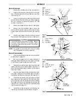
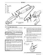
Turbine Alternator Removal
1.
Remove the power cartridge from the gun
handle as described under Power Cartridge
Replacement.
2.
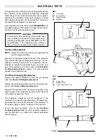
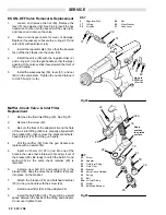
Carefully twist the turbine alternator (1a)
coun-
terclockwise and pull it off the power supply (3) until
just disengaged from the coupling (MM). Then con-
tinue to slowly pull the turbine alternator away from
the power supply, disconnecting the 3-wire connec-
tor (NN). See Fig 21.
3.
Using an ohmmeter, test the coil in the turbine al-
ternator (1a). Measure the resistance between the
two outer terminals of the 3-wire connector (NN).
The resistance should be 3 to 5 ohms. If the reading
varies from this value, replace the alternator.
4.
Measure the resistance between each outer ter-
minal of the 3-wire connector (NN) and the turbine
alternator housing (1a). The resistance should be in-
finite. If the resistance is not infinite, replace the
alternator.
5.
Partially connect the 3-wire connector (NN) onto
the prongs inside the power supply (3). See Fig 21.
Using a small screwdriver, push the connector onto
the prongs until seated.
6.
Slide the turbine alternator (1a) onto the power
supply, being sure to align the coupling between the
power supply and the turbine alternator housing.
Then twist the turbine alternator
clockwise to lock the
coupling.
7.
Install the power cartridge in the gun handle as
described under Power Cartridge Replacement.
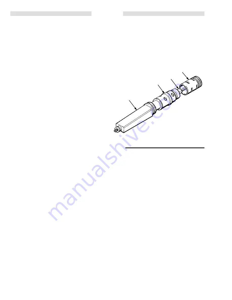
Fig 21
KEY
1a
Alternator
3
Power Supply
MM
Coupling
NN
3–Wire Connector
3
NN
1a
MM
Summary of Contents for PRO AA4000
Page 2: ... ...


