307-706 31
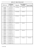
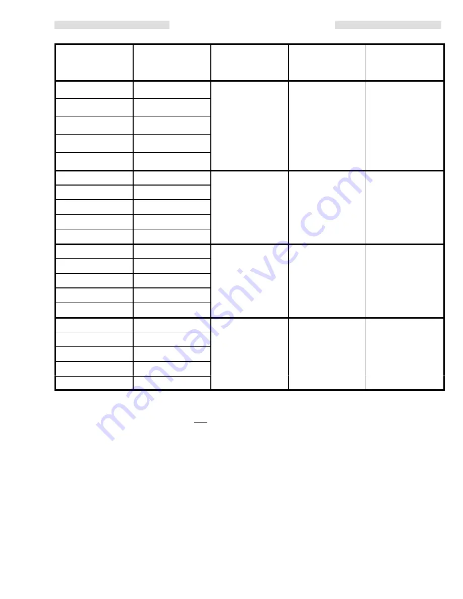
SPRAY TIP SELECTION CHART
Part Number
Fan Width at
300 mm (12 in.)
mm (in.)
Orifice Size
mm (in.)
Light to Medium
Viscosity*
ml/min (fl oz/min)
Heavy
Viscosity*
liters/min ((fl oz/min)
219–319
150–200 (6–8)
0.483 (0.019)
800 (27.0)
600 (20.3)
219–419
200–250 (8–10)
219–519
250–300 (10–12)
219–619
300–350 (12–14)
219–719
350–400 (14–16)
219–421
200–250 (8–10)
0.533 (0.021)
1000 (33.8)
800 (27.0)
219–521
250–300 (10–12)
219–621
300–350 (12–14)
219–721
350–400 (14–16)
219–821
400–450 (16–18)
219–423
200–250 (8–10)
0.584 (0.023)
1200 (40.6)
970 (32.8)
219–523
250–300 (10–12)
219–623
300–350 (12–14)
219–723
350–400 (14–16)
219–823
400–450 (16–18)
219–425
200–250 (8–10)
0.635 (0.025)
1500 (50.7)
1200 (40.6)
219–525
250–300 (10–12)
219–625
300–350 (12–14)
219–725
350–400 (14–16)
219–825
400–450 (16–18)
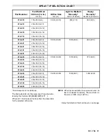
*Fluid Output at 41 bar (600 psi).
The fluid output (Q) at other pressures (P) can be calcu-
lated by this formula: Q= (0.041) (QT) (
P )
Where QT = Fluid output (fl oz/min) from the above table
for the selected orifice size.
NOTE: Other tips are available on special work order. Al-
low 4 to 6 weeks for delivery. The maximum ori-
fice size is 0.635 mm (0–025 in).
Spray Tip Selection Chart continued on next page.
Summary of Contents for PRO AA4000
Page 2: ... ...

