background image

Installation

309457G

9

Installation

Install the System

F

IG

. 2. shows a typical electrostatic air spray system, 

and F

IG

. 3. shows possible system options. It is not an 

actual system design. For assistance in designing a sys-
tem to suit your particular needs, contact your Graco 
distributor.

Basic Guidelines

When spraying waterborne fluids electrostatically:

The gun must be connected to a voltage isolation 
system, which isolates the fluid supply from ground 
and allows voltage to be maintained at the tip of the 
gun.

The gun must be connected to a voltage isolation 
system that will discharge the system voltage when 
the gun is not in use.

All components of the isolation system that are 
charged to high voltage must be contained within a 
fence or enclosure that prohibits persons from mak-
ing contact with the high voltage components before 
the system voltage is discharged.

The gun turbine air supply must be interlocked with 
the isolation system to shut off the turbine air supply 
anytime the isolation system enclosure or safety 
fence is opened.

The voltage isolation system must be interlocked 
with the spray area entrance to automatically dis-
charge the voltage and ground the fluid whenever 
someone enters the spray area.

The system should not have any severe arcing 
occurring when the isolation mechanism opens and 
closes. Severe arcing will shorten the life of the sys-
tem components.

Graco Waterborne Fluid Hose

Use a Graco waterborne fluid hose between the voltage 
isolation system fluid outlet and the gun fluid inlet. See 
Accessories on page 56 for available hoses. The hose 
consists of an inner PTFE tube, a conductive layer cov-
ering the PTFE tube, and an outer cover.

If a hose failure occurs where high voltage arcs through 
the inner tube, voltage will be discharged to ground 
through the conductive hose layer. When properly 
installed, the conductive hose layer is grounded through 
its connection to the grounded enclosure.  

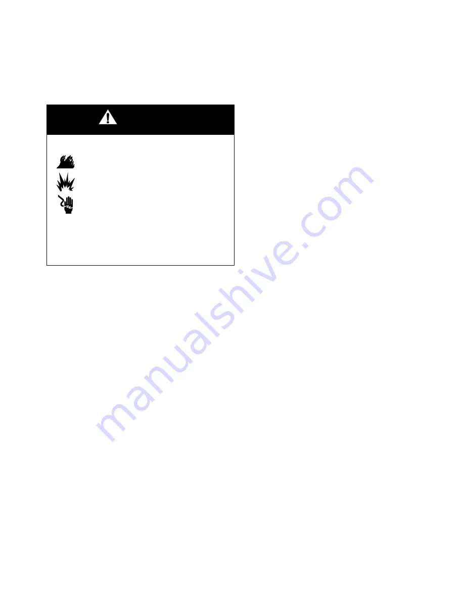
WARNING

Fire, Explosion, and Electric Shock Hazard

Installing and servicing this equipment 
requires access to parts which may cause 
electric shock or other serious injury if work 
is not performed properly.

Do not install or service this equipment 

unless you are trained and qualified. 

Be sure your installation complies with all 

National, State and Local safety and fire 
codes, NFPA 33, NEC 504 and 516, and 
OSHA standard 1910.107. 

Summary of Contents for PRO Auto Xs

Page 1: ...et at least one of the following conditions for non flammability The fluid has a flash point above 140 F 60 C and a maximum organic solvent concentration of 20 by weight per ASTM Standard D93 The fluid does not sustain burning when tested per ASTM Standard D4206 Sustained Burn Test NOTE Fluid hose must be ordered separately For patent information see www graco com patents Important Safety Instruct...

Page 2: ...ttern 23 Adjust the Electrostatics 25 Spraying 25 Triggering the Fluid Alone 25 Shutdown 25 Maintenance 26 Daily Care and Cleaning 26 Clean the Air Cap and Fluid Nozzle 28 Check for Fluid Leakage 29 Electrical Tests 30 Test Gun Resistance 30 Test Power Supply Resistance 31 Test Electrode Resistance 32 Troubleshooting 33 Voltage Loss Troubleshooting 33 Spray Pattern Troubleshooting 36 Gun Operation...

Page 3: ...anytime the isolation system enclosure is opened The voltage isolation system must be interlocked with the spray area entrance to automatically discharge the voltage and ground the fluid whenever someone enters the spray area The areas of the waterborne hose that are accessible to personnel must be covered by the conductive hose layer The area of the hose that is not covered by the conductive hose...

Page 4: ...e all ignition sources such as pilot lights cigarettes and static arcs from plastic drop cloths Do not plug in or unplug power cords or turn lights on or off in the spray area Check gun resistance daily See Test Gun Resistance on page 30 Only use this equipment to spray non flammable waterborne fluids as defined on the front cover of this manual Only flush purge or clean the electrostatic waterbor...

Page 5: ...s that are compatible with the equipment wetted parts See the Techni cal Data section of all equipment manuals Read the fluid and solvent manufacturer s warn ings Route the hoses away from traffic areas sharp edges moving parts and hot surfaces Do not expose Graco hoses to temperatures above 180 F 82 C or below 40 F 40 C Wear hearing protection when operating this equipment Comply with all applica...

Page 6: ...re some of the energy while spraying and retain some of that energy after the spray gun is shut off It is not safe to touch the front end of the gun until the stored energy is discharged The amount of time it takes to discharge the energy depends on the system design Follow the Fluid Voltage Discharge and Grounding Procedure on page 21 before approaching the front of the gun A safe well designed v...

Page 7: ... internal high voltage power supply The fluid is charged by the spray gun electrode The charged fluid is attracted to the nearest grounded object wrapping around and evenly coating all surfaces The turbine air is exhausted into the shroud and out the back of the manifold through the exhaust fitting EXH The exhaust air helps keep contaminants out and helps keep the gun clean Changing the kV Setting...

Page 8: ... Shroud E Mounting Bracket F Manifold G Turbine H Power Supply J Electrode Manifold Markings A1 Atomization Air Inlet Fitting A2 Fan Air Inlet Fitting CYL Cylinder Air Inlet Fitting EXH Shroud Exhaust Outlet Fitting FO Fiber Optic Fitting shipped unassembled KV1 kV Switch 1 Air Inlet KV2 kV Switch 2 Air Inlet P1 Fluid Supply Inlet Fitting P2 Not Used TA Turbine Air Inlet Fitting ...

Page 9: ...t be interlocked with the spray area entrance to automatically dis charge the voltage and ground the fluid whenever someone enters the spray area The system should not have any severe arcing occurring when the isolation mechanism opens and closes Severe arcing will shorten the life of the sys tem components Graco Waterborne Fluid Hose Use a Graco waterborne fluid hose between the voltage isolation...

Page 10: ...d the buildup of flammable or toxic vapors when spraying flushing or cleaning the gun Do not operate the gun unless ventilation fans are operating A Air Hose Ground Wire B Graco Grounded Turbine Air Hose TA C Atomizing Air Hose 3 8 in 10 mm OD A1 D Fan Air Hose 3 8 in 10 mm OD A2 E Cylinder Air Hose 5 32 in 4 mm OD CYL F Graco Waterborne Fluid Hose P1 G To Isolated Fluid Supply System H Auto PRO X...

Page 11: ...A K K See above K X KV1 L L L Manifold Back KV mA 85 0 KV TI1797A Q T NOTE A maximum of two splices with a total of 108 ft 33 m of cable can be used For the strongest light signals use a minimum number of bulkhead splices See Accessories on page 57 Non Hazardous Hazardous Area H U R P S V Do not use the Display Module readings to determine if your system is discharged The display modules only disp...

Page 12: ... quick exhaust port Install the Gun and Mounting Bracket 1 Loosen the mounting bracket s two set screws 103 and slide the bracket 102 onto a 1 2 in 13 mm mounting rod See FIG 4 2 Position the gun and tighten the two set screws NOTE For added positioning reliability insert a 1 8 in 3 mm locating pin into the slot NN in the bracket and through a hole in the rod See the detail in FIG 4 Fig 4 Mounting...

Page 13: ...r serious injury you must use the red colored Graco grounded air hose for the turbine air supply hose and you must connect the hose ground wire to a true earth ground Do not use the black or grey colored Graco air hoses A1 Atomization Air Inlet Fitting Connect a 3 8 in 10 mm OD tube between this fitting and the air supply A2 Fan Air Inlet Fitting Connect a 3 8 in 10 mm OD tube between this fitting...

Page 14: ...se Dimensions 3 Inspect the o ring R on the barrel fitting F of the hose Replace if worn or damaged See FIG 7 4 Lubricate the o ring R on the barrel fitting F with dielectric grease Screw the fitting into the fluid inlet of the gun barrel 9 and tighten 5 Unscrew the strain relief nut N from the hose fer rule M and slide the nut up the hose CAUTION The Graco warranty is void if the spray gun is con...

Page 15: ...Installation 309457G 15 Fig 7 Connect the Waterborne Fluid Hose TI1793A TI1802A F C R P1 9 N M N M Ferrule M and nut N are part of the waterborne hose assembly purchase separately ...

Page 16: ...ed Fluid Supply WARNING Electric Shock Hazard To maintain grounding continuity the con ductive hose layer C must be engaged in the ferrule M when the nut N is tight ened Failure to properly install the hose in the fitting could result in an electric shock WARNING Electric Shock Hazard To reduce the risk of electric shock the areas of the waterborne fluid hose that are accessible to personnel durin...

Page 17: ...fitting 5 until it bot toms out Tighten the nut AA to secure the cable Fig 10 Fiber Optic Cable NOTE Most of the fiber optic light transmission loss occurs at the bulkhead splices For the strongest light signals use a minimum number of bulkhead splices A maximum of two splices with a total of 108 ft 33 m of cable is recommended 4 See manual 308265 to install a Graco ES Display Module WARNING Elect...

Page 18: ...rly grounded All persons entering the spray area shoes must have conductive soles such as leather or personal grounding straps must be worn Do not wear shoes with non conductive soles such as rubber or plastic Object being sprayed keep the workpiece hangers clean and grounded at all times Resistance must not exceed 1 megohm The floor of the spray area must be electrically con ductive and grounded ...

Page 19: ...ons and be sure the turbine air hose ground wire is connected to a true earth ground If the resistance is still too high replace the turbine air hose Fig 11 Check Gun Grounding WARNING Fire Explosion and Electric Shock Hazard Megohmmeter Part No 241079 AA see FIG 11 is not approved for use in a haz ardous area To reduce the risk of sparking do not use the megohmmeter to check elec trical grounding...

Page 20: ...posed tubing and hoses at the back of the manifold See FIG 12 2 Route the exhaust tube YY outside the cover This enables you to monitor the exhaust tube for the presence of any paint or solvent See Check for Fluid Leakage on page 29 Strap down the exhaust tube to prevent it from moving around Fig 12 Fabric Cover TI1792A ti1787A YY YY XX ...

Page 21: ... the regulator air inlet NOTE The air shut off device must bleed the air out of the system 4 Trigger the gun into a grounded metal waste con tainer to relieve the fluid pressure 5 Turn off all remaining air supplies to the gun 6 Turn off the main air supply by closing the bleed type master air valve on the main air supply line Leave the valve closed until you are ready to spray again WARNING Elect...

Page 22: ...on of the gun s electrical compo nents has been checked as instructed in Elec trical Tests on page 30 All fluid hose connections are tight Ventilation fans are operating properly Workpiece hangers are clean and grounded All debris including flammable fluids and rags is removed from the spray area All conductive objects in the spray area are electrically grounded and the floor of the spray area is ...

Page 23: ...ve 140 F 60 C and a maximum organic solvent concentration of 20 by weight per ASTM Standard D93 The fluid does not sustain burning when tested per ASTM Standard D4206 Sustained Burn Test WARNING Electric Shock Hazard Contact with the charged components of the spray gun will cause an electric shock Do not touch the gun nozzle or electrode or come within 2 ft 0 61 m of the front of the gun during op...

Page 24: ...0 21 MPa at the gun manifold 6 Use the air pressure regulator on the fan air supply line A2 to adjust the pattern size For the most efficiency always use the lowest air pressure possible When increasing to a wide flat pattern it may be necessary to increase the supply of fluid to the gun to maintain the same amount of cover age over a large area See Spray Pattern Troubleshooting on page 36 to corr...

Page 25: ...oltage setting activate the solenoids controlling the KV1 and KV2 ports See Changing the kV Setting on page 7 Triggering the Fluid Alone 1 Shut off and relieve the air pressure to the atomiza tion A1 and fan A2 air lines using the bleed type air shutoff valves 2 Apply 50 psi 3 5 bar 0 35 MPa air pressure to the cylinder air fitting CYL to trigger the fluid Shutdown 1 Discharge the system voltage p...

Page 26: ... in the air passages could cause the gun to malfunction and could draw current and reduce the electrostatic effect Fluid in the power supply cavity can reduce the alternator life Whenever possible point the gun down when cleaning it Do not use any cleaning method which could allow fluid into the gun air passages Do not immerse the gun in fluid Do not point the gun up while cleaning it Do not wipe ...

Page 27: ...d See Electrode Replacement on page 42 Check for fluid leakage from the gun and fluid hoses See Check for Fluid Leakage on page 29 Tighten fittings or replace equipment as needed Flush the gun before changing colors and whenever you are done operating the gun WARNING Pressurized Equipment Hazard To reduce the risk of an injury follow the Pressure Relief Procedure on page 21 before doing any mainte...

Page 28: ... soft bristle brush and solvent or submerge the air cap in suitable solvent and wipe it clean 7 Slide the shroud 2 onto the gun 8 Carefully install the air cap 3 Be sure to insert the electrode 7 through the center hole of the air cap Rotate the air cap to the desired position 9 Make sure the u cup 1a is in place on the retaining ring 1 The lips must face forward Tighten the retaining ring until t...

Page 29: ... fluid tube connections or fluid packing leakage If fluid is seen in these areas stop spraying immediately Discharge the voltage page 21 relieve the pressure page 21 and then remove the gun for repair Fig 16 Check for Fluid Leakage WARNING Fire and Explosion Hazard If any fluid leakage from the gun is detected stop spraying immediately Fluid leakage into the gun shroud could cause fire or explosio...

Page 30: ...test If in range refer to Electrical Troubleshooting on page 38 for other possible causes of poor perfor mance Fig 17 Test Gun Resistance WARNING Fire Explosion and Electric Shock Hazard Megohmmeter Part No 241079 AA see FIG 17 is not approved for use in a haz ardous area To reduce the risk of sparking do not use the megohmmeter to check elec trical grounding unless The gun has been removed from t...

Page 31: ...pring 12b See FIG 18 4 The resistance should be 95 105 megohms If out side this range replace the power supply If in range proceed to the next test 5 If you still have problems refer to Electrical Trou bleshooting on page 38 for other possible causes of poor performance or contact your Graco distribu tor 6 Be sure the spring 12b is in place before reinstall ing the power supply Fig 18 Test Power S...

Page 32: ...Troubleshooting on page 38 for other possible causes of poor perfor mance or contact your Graco distributor 4 Remove the electrode 7 page 42 Measure the resistance between the contact E and the elec trode wire F The resistance should be 20 30 meg ohms If out of range replace the electrode See FIG 20 5 Make sure the metal contact C in the barrel the nozzle contact ring 4a FIG 21 and the electrode c...

Page 33: ...aces Fluid in the air passages Waterborne Fluid Hose Dielectric failure of hose pin hole leak through PTFE layer Air gap in the fluid column between the gun and iso lated fluid supply causing a low voltage reading on the isolation system voltage meter Voltage Isolation System Fluid leakage Dielectric breakdown of hoses seals or connec tions Isolators not functioning properly WARNING Electric Shock...

Page 34: ...or any visible fluid leak age and repair any fluid leaks that are found Pay special attention to the following areas Packing area of the spray gun Fluid hose check for leakage or any bulges in the outer cover which may indicate an internal leak Internal voltage isolation system components Tests If you still have no voltage separate the spray gun and hose from the voltage isolation system and check...

Page 35: ...or tion of the fluid tube Inspect the end of the hose connected to the voltage isolation system Look for cuts or nicks Make sure the hose is properly stripped Restrip or replace the hose Fluid packings Remove the packing assembly from the gun as instructed on page 43 and look for signs of fluid leakage or any blackened areas which would indicate arcing is occurring along the packing rod Fluid hose...

Page 36: ...dirty damaged nozzle seat Clean or replace nozzle page 41 Air in fluid supply Check fluid source Refill Improper spray pattern Damaged nozzle or air cap Replace page 41 Fluid buildup on air cap or nozzle Clean See page 28 Fan air pressure too high Decrease Fluid too thin Increase viscosity Fluid pressure too low Increase Fan air pressure too low Increase Fluid too thick Reduce viscosity Too much f...

Page 37: ...le 4 Tighten see page 41 Damaged nozzle o ring 4b Replace see page 41 Gun does not spray Low fluid supply Add fluid if necessary Damaged air cap 3 Replace see page 41 Dirty or clogged fluid nozzle 4 Clean see page 41 Damaged fluid nozzle 4 Replace see page 41 Piston 34 not actuating Check cylinder air Check piston u cup 34d see page 45 Actuator arm 29 is out of position Check actuator arm and nuts...

Page 38: ...workpiece hangers Faulty gun resistance See Test Gun Resistance on page 30 Low fluid resistivity Check fluid resistivity page 20 Fluid leaks from the packing 8d and causes a short Clean the packing rod cavity Replace the packing rod See page 44 Faulty turbine alternator Be sure the plug is in place on the back of the turbine alternator hous ing Remove and test the turbine alternator See page 50 Th...

Page 39: ...age 40 5 Remove the gun from the worksite Repair area must be clean WARNING Fire Explosion and Electric Shock Hazard To reduce the risk of a fire explosion or electric shock Follow the Fluid Voltage Discharge and Grounding Procedure on page 21 before flushing checking or servicing the system and whenever you are instructed to discharge the voltage Clean all the parts with a non flammable solvent a...

Page 40: ...and spring 105 are in place on the manifold See FIG 22 Inspect the parts for damage and replace them as needed 2 Secure the gun to the manifold by tightening the three screws 106 3 Secure the gun to the mounting bracket 102 by tightening the bottom screw 31 4 Make sure the fittings and barrel are clean and dry then reconnect the waterborne fluid hose page 14 5 Reinstall the gun shroud 2 and air ca...

Page 41: ...of the air cap Rotate the air cap to the desired position 7 Make sure the u cup 1a is in place on the retaining ring 1 The lips must face forward Tighten the retaining ring until the air cap is held firmly in place you should not be able to rotate the air cap horns by hand 8 Test gun resistance page 30 9 Install the gun onto the manifold and bracket See page 40 CAUTION Hold the front end of the gu...

Page 42: ...y low strength purple Loctite or equivalent thread sealant to the electrode and packing rod threads Install the electrode finger tight Do not overtighten 5 Install the fluid nozzle page 41 6 Test gun resistance page 30 7 Install the gun shroud 2 and air cap page 41 8 Install the gun onto the manifold and bracket See page 40 Fig 24 Electrode Replacement CAUTION To avoid damaging the plastic threads...

Page 43: ...m nut and actuator arm 4 Remove the fluid nozzle 4 and electrode 7 See pages 41 and 42 5 Remove the packing rod 8 using the multi tool 40 6 Check all parts for wear or damage and replace if necessary NOTE Before installing the packing rod clean the inter nal surface of the barrel 9 with a soft cloth or brush Check for marks from high voltage arcing If marks are present replace the barrel Fig 25 Fl...

Page 44: ... shown Generously apply dielectric grease to the outside of the spacer 3 Place the rod packing 8d packing spreader 8c and housing 8f on the packing rod 8h 4 Lightly tighten the packing nut 8e The packing nut is properly tightened when there is 3 lb 13 3 N of drag force when sliding the packing housing 8f assembly along the rod Tighten or loosen the pack ing nut as needed 5 Install the o ring 8a on...

Page 45: ... Part No 111265 Do not over lubricate 7 Align the two stems 34c with the holes in the gun body and press the piston assembly into the back of the gun until it bottoms 8 Install and adjust the actuator arm page 46 Fig 28 Piston O Rings Table 5 Piston O Rings Description Function Shaft O Ring 34g Seals cylinder air along the piston rod 34b Replace if air leaks along rod TI1800A 28 29 30 34b Front O ...

Page 46: ...gap between the actuator arm 29 and the fluid packing rod nut E which allows the atomizing air to actuate before the fluid See FIG 29 3 Tighten the adjustment nut 30 against the actuator arm 29 Check that the 0 125 in 3 mm gap has been maintained In addition there should be 3 4 mm of electrode needle travel when the gun is trig gered Adjust the jam nut position to obtain these dimensions 4 Test gu...

Page 47: ...Remove the jam nut 28 and actuator arm 29 See page 45 5 Loosen the three screws 10 33 See FIG 30 6 Hold the gun body 32 with one hand and pull the barrel 9 straight off the body See FIG 30 Fig 30 Barrel Removal Fig 31 Disconnect Fluid Tube CAUTION To avoid damaging the power supply 12 pull the gun barrel 9 straight away from the gun body 32 If necessary gently move the gun barrel from side to side...

Page 48: ... oppositely and evenly about a half turn past snug 4 Assemble the fluid tube 19 into the fluid fitting 23 Ensure that the ferrules 21 22 are in place Tighten the nut 20 5 Install and adjust the actuator arm 29 and jam nut 28 See page 46 6 Test gun resistance page 30 7 Install the gun shroud 2 and air cap page 41 8 Install the gun onto the manifold and bracket See page 40 Fig 32 Barrel Installation...

Page 49: ...uit 39 from the power supply 5 Check the power supply resistance page 31 Replace if necessary 6 Connect the 6 pin flexible circuit 39 to the power supply 7 Connect the 3 wire connector GG Slide the alter nator 13 down onto the power supply 12 8 Lubricate the alternator o ring 13a with non sili cone grease Part No 111265 Do not over lubri cate 9 Lubricate the power supply o ring 12a with dielec tri...

Page 50: ...assembly page 49 3 Disconnect the alternator from the power supply page 49 4 Measure resistance between the two outer termi nals of the 3 wire connector GG it should be 2 5 3 5 ohms If outside this range replace the alter nator coil 5 Follow the bearing replacement procedure in the bearing kit manual 308034 6 Install the alternator on the power supply page 49 7 Install the power supply alternator ...

Page 51: ...Repair 309457G 51 ...

Page 52: ...es A for waterborne coatings TI1777A ti1601a 7 12 34a 35 9 4a 4b 10 12a 12b 32 2 34d 1 3 4 8 11 13 13e 13a 34c 34f 34e 34g 34b 30 27 26 29 28 31 25 TI1481a 13a 13b 13b 13c Ref No 13 Alternator De tail 13d 13e 8a 8b 8c 8d 8e 8f 8g 8h Ref No 8 Packing Rod De 39 1a 40 41 33 51 ...

Page 53: ...PPLY 60 kV includes 12a 12b 1 12a 103337 O RING fluoroelastomer 1 12b 197624 SPRING compression 1 13 244555 TURBINE alternator includes 13a 13e 1 13a 110073 O RING fluoroelastomer 1 13b 223688 BEARING KIT includes front and rear bearings and fan 1 13c 244577 COIL 1 13d 111745 RING retaining 1 13e 198821 PAD pressure 2 15 107460 TOOL wrench ball end not shown 1 16 179791 TAG warning not shown repla...

Page 54: ... and cards are available at no cost 35 244938 MANIFOLD see separate parts list on page 55 1 37 245265 CIRCUIT flexible 1 39 276741 MULTI TOOL 1 40 189888 COVER gun box of 10 not shown 1 42 116553 TUBE grease lubricant 1 48 290171 SIGN warning not shown replacement available at no cost 1 56 24A431 KIT wide pattern 1 Ref No Part No Description Qty ...

Page 55: ...0465 SCREW set 2 104 112689 SCREW button hd 2 105 112640 SPRING compression 1 106 197518 SCREW socket hd 10 24 x 3 4 in 19 mm 3 107 111157 FITTING tube 1 108 186845 FITTING turbine 1 109 110078 FITTING tube fluid 2 110 112646 PLUG 1 112 197925 GASKET manifold 1 113 108290 SCREW machine 2 114 189365 CAP kV HI LO 2 115 198764 RESTRICTOR 1 116 244772 PISTON includes 116a 2 116a 112085 O RING 1 117 11...

Page 56: ...ir to gun on or off 224754 1 4 npsm m x 1 4 npsm f left hand thread Fluid Line Accessories Shielded Waterborne Fluid Hose 100 psi 7 bar 0 7 MPa Maximum Working Pressure PTFE 1 4 in 6 mm ID 245327 25 ft 7 6 m 245328 36 ft 11 m Unshielded Waterborne Fluid Hose 100 psi 7 bar 0 7 MPa Maximum Working Pressure PTFE 1 4 in 6 mm ID See manual 308688 for instal lation requirements 245329 25 ft 7 6 m 245330...

Page 57: ...y Module See 308265 Fiber Optic Y Cables See item T in FIG 3 on page 11 For use with 224117 Display Module only Connect gun manifold and display module or bulkhead connector and display module See 308265 224682 25 ft 7 6 m 224684 50 ft 15 m 224686 100 ft 30 5 m Remote Voltage Display 189762 Battery operated meter displays actual spraying voltage remote mount outside hazardous area Connects to gun ...

Page 58: ...electric Grease 116553 1 oz 28 g tube of dielectric grease for the power supply o ring 12a some packing rod parts 8 and certain fluid fittings Gun Valve Lubricant 111265 4 oz 113 g tube of sanitary non silicone lubricant for fluid seals and wear areas Alternator Bearing Kit 223688 To repair the turbine alternator Cleaning Brush 105749 For cleaning air cap and fluid nozzle ...

Page 59: ...0 psi 0 28 MPa 2 8 bar 90 4 dB A at 100 psi 0 7 MPa 7 bar 105 4 dB A Sound Pressure measured 1 m from gun at 40 psi 0 28 MPa 2 8 bar 87 dB A at 100 psi 0 7 MPa 7 bar 99 dB A Turbine air inlet fitting left hand thread 1 4 npsm m Atomizing air inlet fitting 3 8 in OD nylon tube Fan air inlet fitting 3 8 in OD nylon tube Cylinder air inlet fitting 5 32 in OD nylon tube Hi Lo voltage selector air inle...

Page 60: ...ee of charge any defective parts The equipment will be returned to the original purchaser transportation prepaid If inspection of the equipment does not disclose any defect in material or workmanship repairs will be made at a reasonable charge which charges may include the costs of parts labor and transportation THIS WARRANTY IS EXCLUSIVE AND IS IN LIEU OF ANY OTHER WARRANTIES EXPRESS OR IMPLIED I...

Reviews: