


Repair
Fluid
Fluid
Fluid Tube
Tube
Tube Removal
Removal
Removal and
and
and Replacement
Replacement
Replacement
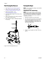
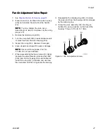
1.
Remove the nut (22) from the bracket (20).
2.
Loosen the fitting (9) to remove the fluid tube
(14) from the barrel (1).
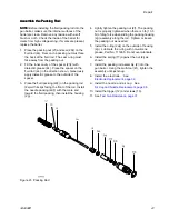
3.
Apply dielectric grease (44) to the threads of the
fitting (9) and the o-ring (10). Ensure the ferrules
(7, 8) are in place.
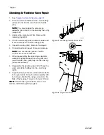
NOTE:
NOTE:
NOTE: On 40 kV guns, the o–ring (10★) is not
used, and ferrules (7★) and (8★) are part of the
top fitting (9).
NOTE:
NOTE:
NOTE: On 60 and 85 kV kV guns, check that the
sleeve (SL) is in place near the top of the fluid
tube.
4.
Slide the fitting (9) onto the fluid tube (14) and
thread the fitting into the barrel (1). Torque to
25–35 in-lb (2.8–3.9 N•m).
5.
With the ferrules (7, 8) seated to the bracket (20),
screw the nut (22) securely onto the bracket.
Make sure the top fitting remains tight.
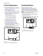
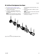
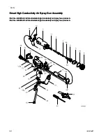
Figure 31 Fluid Tube
46
3A2494D


