background image

Air Caps and Fluid Nozzles

Air

Air

Air Consumption

Consumption

Consumption Charts

Charts

Charts

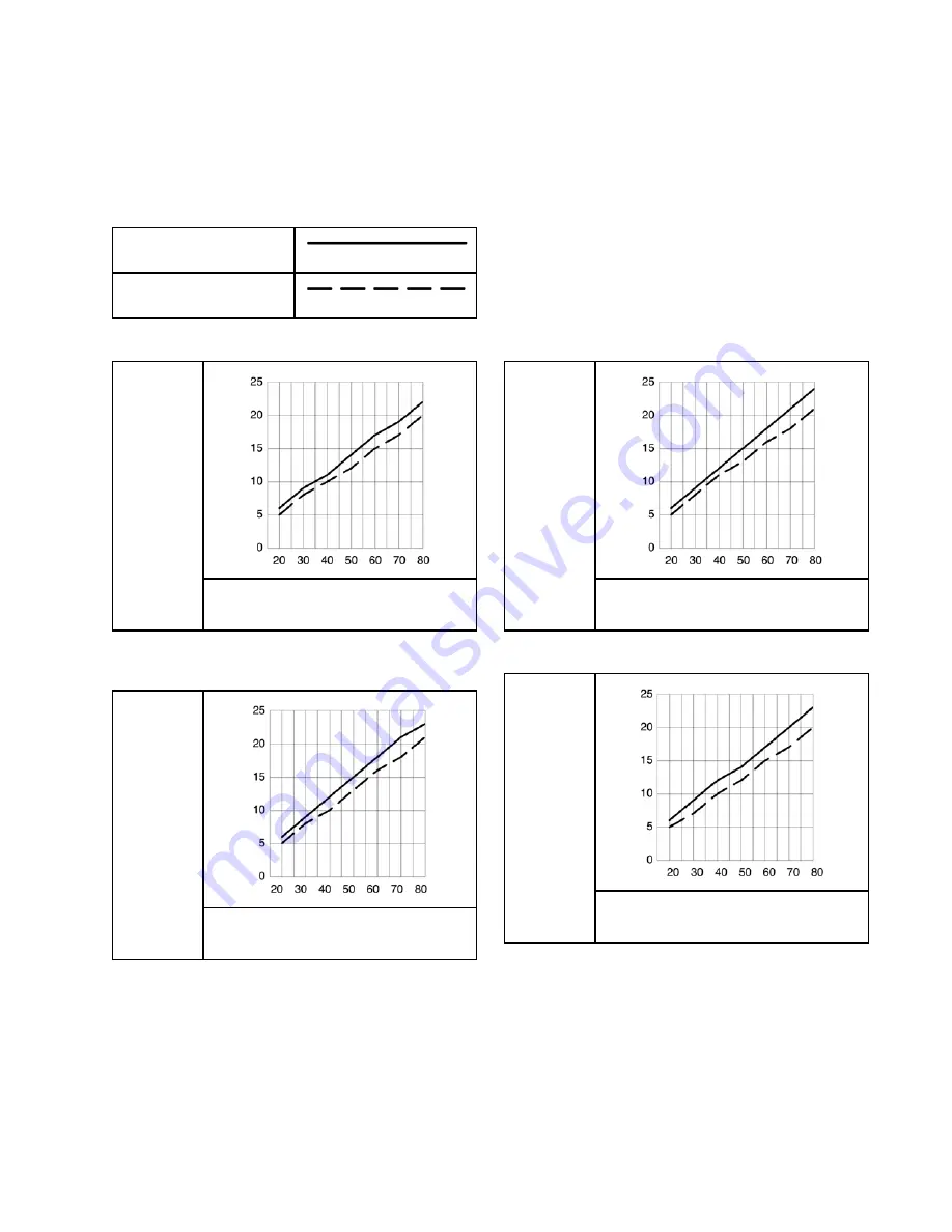
Key

Key

Key to

to

to Air

Air

Air Consumption

Consumption

Consumption Charts

Charts

Charts

TEST

TEST

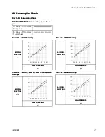
TEST CONDITIONS:

CONDITIONS:

CONDITIONS: Fan valve fully open; 85 kV

gun.

5/16 in. x 25 ft (8 mm x
7.6 m) hose

5/16 in. x 50 ft (8 mm x
15.2 m) hose

Table

Table

Table 11

11

11 ... 24N438

24N438

24N438 Air

Air

Air Cap

Cap

Cap

AIR

AIR

AIR CON-

CON-

CON-

SUMPTION

SUMPTION

SUMPTION

scfm

WALL

WALL

WALL PRESSURE

PRESSURE

PRESSURE

psi

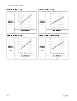
Table

Table

Table 12

12

12 ... 24N376,

24N376,

24N376, 24N276,

24N276,

24N276, 24N277,

24N277,

24N277, and

and

and 24N278

24N278

24N278

Air

Air

Air Caps

Caps

Caps

AIR

AIR

AIR CON-

CON-

CON-

SUMPTION

SUMPTION

SUMPTION

scfm

WALL

WALL

WALL PRESSURE

PRESSURE

PRESSURE

psi

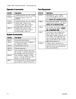
Table

Table

Table 13

13

13 ... 24N439

24N439

24N439 Air

Air

Air Cap

Cap

Cap

AIR

AIR

AIR CON-

CON-

CON-

SUMPTION

SUMPTION

SUMPTION

scfm

WALL

WALL

WALL PRESSURE

PRESSURE

PRESSURE

psi

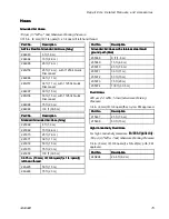
Table

Table

Table 14

14

14 ... 24N279

24N279

24N279 Air

Air

Air Cap

Cap

Cap

AIR

AIR

AIR CON-

CON-

CON-

SUMPTION

SUMPTION

SUMPTION

scfm

WALL

WALL

WALL PRESSURE

PRESSURE

PRESSURE

psi

3A2494D

71

Summary of Contents for Pro Xp 3A2494D

Page 1: ...tions Locations using using using Group Group Group IIA IIA IIA spray spray spray materials materials materials For For For professional professional professional use use use only only only Important Important Important Safety Safety Safety Instructions Instructions Instructions Read all warnings and instructions in this manual Save Save Save these these these instructions instructions instruction...

Page 2: ... Barrel Removal 42 Barrel Installation 42 Power Supply Removal and Replacement 43 Alternator Removal and Replacement 44 Fluid Tube Removal and Replacement 46 Fan Air Adjustment Valve Repair 47 Atomizing Air Restrictor Valve Repair 48 ES On Off and Fluid Adjustment Valve Repair 49 Air Valve Repair 50 Smart Module Replacement 51 Air Swivel and Exhaust Valve Replacement 52 Parts 53 Standard Air Spray...

Page 3: ...tandard Standard Standard Coatings Coatings Coatings High High High Conductivity Conductivity Conductivity High High High Wear Wear Wear Increased Increased Increased Transfer Transfer Transfer Efficiency Efficiency Efficiency L40T10 40 L40T14 40 L40T15 40 L40T16 40 L60T10 60 L60T11 60 L60T12 60 L60T16 60 L60M10 60 L60M12 60 L60M16 60 L85T10 85 L85T16 85 L85M10 85 L85M16 85 II II II 2 2 2 G G G EE...

Page 4: ...must not exceed 1 megohm See Grounding Grounding Grounding instructions Only use grounded Graco conductive air supply hoses Do not use pail liners unless they are conductive and grounded Stop Stop Stop operation operation operation immediately immediately immediately if static sparking occurs or you feel a shock Do not use equipment until you identify and correct the problem Check gun resistance h...

Page 5: ... to clean plastic structural or pressure containing parts See Technical Technical Technical Data Data Data in this and all other equipment instruction manuals Read fluid and solvent manufacturer s MSDSs and recommendations TOXIC TOXIC TOXIC FLUID FLUID FLUID OR OR OR FUMES FUMES FUMES Toxic fluids or fumes can cause serious injury or death if splashed in the eyes or on skin inhaled or swallowed Re...

Page 6: ...Do not leave the work area while equipment is energized or under pressure Turn off all equipment and follow the Pressure Pressure Pressure Relief Relief Relief Procedure Procedure Procedure when equipment is not in use Check equipment daily Repair or replace worn or damaged parts immediately with genuine manufacturer s replacement parts only Do not alter or modify equipment Alterations or modifica...

Page 7: ...the alternator turbine and the rest of the air atomizes the fluid being sprayed The alternator generates power which is converted by the power cartridge to supply high voltage to the gun s electrode The pump supplies fluid to the fluid hose and gun where the fluid is electrostatically charged as it passes the electrode The charged fluid is attracted to the grounded workpiece wrapping around and ev...

Page 8: ...e Air Caps and Fluid Nozzles page 68 for avail able sizes E Electrode Needle Supplies electrostatic charge to the fluid F Fan Air Adjust ment Valve Adjusts fan size and shape Can be used to decrease pattern width G Atomizing Air Restrictor Valve Restricts air cap air flow Replace with plug included if desired Item Item Item Descrip Descrip Descrip tion tion tion Purpose Purpose Purpose H Fluid Ad ...

Page 9: ...ses Hz Hz Hz Indicator Indicator Indicator The Hz indicator functions the same as the ES indicator on standard guns The indicator lights to show the alternator speed status and has three colors Green indicates the alternator speed is correct If the indicator changes to amber after 1 second increase the air pressure If the indicator changes to red after 1 second reduce the air pressure Voltage Volt...

Page 10: ... will display the current low voltage setting See Fig 4 and Table 1 on page 10 The possible ranges are 85 kV guns 40 85 kV 60 kV guns 30 60 kV Set the Voltage Adjustment switch VA to LO Press the LO SET button repeatedly to increase the setting in increments of 5 When the display reaches the maximum setting it will return to the minimum setting for your gun Continue pressing the button until you r...

Page 11: ...n Diagnostic Mode voltage is displayed as a number uA Current uA Display Displays actual spraying current of the gun in uA In Operating Mode display is a bar graph In Diagnostic Mode current is displayed as a number LS LO SET button Press momentarily to enter the Low Voltage Setting screen Press and hold for approximately 5 seconds to enter or exit Diagnostic Mode While in Diagnostic Mode press mo...

Page 12: ... of the screen light indicating that the value displayed is in uA See Fig 7 AS Alternator Speed Display In Diagnostic Mode Hz level is displayed as a number See Fig 8 Hz Alternator Speed Indicator In Operating Mode indicator color varies to show the alternator speed status green indicates the alternator speed is at the correct level If the indicator changes to amber after 1 second the alternator s...

Page 13: ...he first screen to appear after entering Diagnostic Mode See Fig 6 and Table 1 on page 10 To enter this screen press and hold the LO SET button for approximately 5 seconds while in the Operating Mode This screen displays the spraying voltage of the gun as a number kV rounded to the nearest 5 kV The two top right LEDs VI of the display panel light indicating that the Voltage kiloVolts Screen is dis...

Page 14: ...reen Low Low Low Voltage Voltage Voltage Lock Lock Lock Screen Screen Screen The Low Voltage Lock Screen is the fourth screen in the Diagnostic Mode See Fig 9 and Table 1 on page 10 To enter this screen press the LO SET button while in the Alternator Speed Hertz Screen This screen displays the status of the Low Voltage Lock If the setting is locked the lock image LK appears to the left of the Lo d...

Page 15: ...cular needs contact your Graco distributor Warning Warning Warning Sign Sign Sign Mount warning signs in the spray area where they can easily be seen and read by all operators An English Warning Sign is provided with the gun Ventilate Ventilate Ventilate the the the Spray Spray Spray Booth Booth Booth Provide fresh air ventilation to reduce the risk of fire or explosion caused by the buildup of fl...

Page 16: ...V on the pump air supply line The bleed type air valve BV is required in your system to shut off air to the pump and relieve air trapped between the valve and the pump after the air regulator is shut off Install an additional bleed type air valve on the main air line MA to isolate the accessories for servicing 5 Install an air bleed valve BV on each gun air supply line to shut off air to the gun s...

Page 17: ...nd threads AL Pump Air Line Lubricator BV Pump Bleed Type Air Shutoff Valve EG Electrostatic Air Spray Gun FD Fluid Drain Valve FF Fluid Filter FL Fluid Supply Line FR Fluid Pressure Regulator Item Item Item Description Description Description FV Fluid Shutoff Valve GR Gun Air Pressure Regulator MA Main Air Supply Line PG Pump Ground Wire PR Pump Air Pressure Regulator SP Supply Pump SV Ventilatio...

Page 18: ... page 38 2 Turn OFF O the ES On Off switch J 3 Shut off the air bleed valve to the gun 4 Check gun resistance See Test Gun Resistance page 31 5 Connect the Graco grounded air hose to the gun air inlet The gun air inlet fitting has left hand threads 6 Follow all steps under Grounding page 21 7 Follow all steps under Check Gun Electrical Grounding page 25 Reading must be less than 1 megohm 8 Verify ...

Page 19: ...or Regulator Setting Setting Setting in in in psi psi psi MPa MPa MPa bar bar bar with with with gun gun gun triggered triggered triggered 15 4 6 55 0 38 3 8 25 7 6 65 0 45 4 5 50 15 3 80 0 56 5 6 18 Check that the ES indicator K Hz indicator on Smart guns is lit See the following table Table Table Table 3 3 3 LED LED LED Indicator Indicator Indicator Colors Colors Colors Indicator Indicator Indic...

Page 20: ...nozzle size is recommended 21 Turn on the air to the gun Turn ON I the ES On Off switch J 22 Spray a test pattern Check the atomization If over atomization occurs at minimum pressure adjust the restrictor valve If atomization is inadequate increase air pressure or decrease fluid flow 23 Adjust the fan air adjustment valve clockwise for a narrower pattern counterclockwise for a wider pattern 24 Spr...

Page 21: ...und the pump fluid source by connecting its ground wire to a true earth ground Electrostatic Air Spray Gun ground the gun by connecting the Graco Grounded Air Hose AH to the gun and connecting the air hose ground wire to a true earth ground See Check Gun Electrical Grounding page 25 Object being sprayed keep the workpiece hangers clean and grounded at all times All electrically conductive objects ...

Page 22: ...rounding straps Do not wear shoes with non conductive soles such as rubber or plastic If gloves are necessary wear the conductive gloves supplied with the gun If non Graco gloves are worn cut off fingers or palm area of gloves to ensure your hand contacts the grounded gun handle Key Key Key to to to Figs Figs Figs 12 15 12 15 12 15 Fig 12 Operator is grounded through bare skin contact with the gun...

Page 23: ...Gun Setup Figure 12 Ground the Operator Figure 13 Ground the Object Being Sprayed 3A2494D 23 ...

Page 24: ...Gun Setup Figure 14 Ground the Gun Figure 15 Ground the Fluid Supply 24 3A2494D ...

Page 25: ...r is available as an accessory to check that the gun is properly grounded 1 Have a qualified electrician check the electrical grounding continuity of the spray gun and air hose 2 Turn OFF O the ES On Off switch 3 Turn off the air and fluid supply to the gun Follow the Pressure Relief Procedure page 27 4 Disconnect the fluid hose 5 Make sure the grounded air hose AH is connected and the hose ground...

Page 26: ...ity cup a stopwatch 1 Completely submerge the viscosity cup in the fluid Lift the cup out quickly starting the stopwatch as soon as the cup is completely removed 2 Watch the stream of fluid coming from the bottom of the cup As soon as there is a break in the stream shut off the stopwatch 3 Record the fluid type elapsed time and size of the viscosity cup 4 If the viscosity is too high or too low co...

Page 27: ... valve having a waste container ready to catch the drainage Leave the pump drain valve open until you are ready to spray again 5 If the nozzle or hose is completely clogged or pressure is not fully relieved slowly loosen the hose end coupling Now clear the nozzle or hose Startup Startup Startup Follow all steps under Gun Setup Checklist page 18 Shutdown Shutdown Shutdown 1 Flush the gun see Flushi...

Page 28: ...ore flushing the gun NOTICE NOTICE NOTICE Do not use methylene chloride as a flushing or cleaning solvent with this gun as it will damage nylon components 1 Turn OFF O the ES On Off switch 2 Follow the Pressure Relief Procedure page 27 3 Change the fluid source to solvent or disconnect the fluid line and connect a solvent supply line to the gun 4 Point the gun into a grounded metal pail Flush unti...

Page 29: ...de of the gun with a compatible solvent Use a soft cloth Point the gun down to prevent solvent from entering the gun passages Do not immerse the gun 5 Remove the air cap 6 Clean the air cap retaining ring and nozzle with a soft brush and compatible solvent 7 If necessary use a toothpick or other soft tool to clean the air cap holes Do not use metal tools 8 Reinstall the air cap Tighten securely 3A...

Page 30: ...27 2 Clean the fluid and air filters 3 Check for fluid leaks Tighten all fittings 4 Clean workpiece hangers Use non sparking tools 5 Check the movement of the trigger and valves Lubricate if necessary 6 Check Gun Electrical Grounding page 25 7 Hang the gun from its hook with the nozzle pointing down 30 3A2494D ...

Page 31: ...sult in serious injury and property damage Test Test Test Gun Gun Gun Resistance Resistance Resistance 1 Flush and dry the fluid passage 2 For For For Model Model Model L40T14 L40T14 L40T14 and and and L40T15 L40T15 L40T15 guns guns guns only only only Test the barrel continuity to verify that the metal pin in the barrel is properly grounded Measure resistance between the metal pin GP and the air ...

Page 32: ...lectrical Troubleshooting page 35 for other possible causes of poor performance or contact your Graco distributor 6 Be sure the spring 11a is in place before reinstalling the power supply Figure 18 Test Power Supply Resistance Test Test Test Electrode Electrode Electrode Resistance Resistance Resistance Remove the electrode 3 See Electrode Replacement page 39 Measure the resistance between the con...

Page 33: ... and fluid Problem Problem Problem Cause Cause Cause Solution Solution Solution No fluid Refill supply Loose dirty damaged nozzle seat Clean or replace nozzle see Clean the Gun Daily page 29 or Air Cap and Nozzle Replacement page 38 Fluttering or spitting spray Air in fluid supply Check fluid source Refill Improper spray pattern Damaged or dirty nozzle or air cap Clean or replace See Air Cap and N...

Page 34: ...r leaks from the front of the gun Air valve is not seating properly See Air Valve Repair page 50 Worn or damaged fluid packing rod or electrode Replace packing rod 2e or electrode 3 See Packing Rod Repair page 40 or Electrode Replacement page 39 Worn fluid nozzle seat Replace nozzle 4 See Air Cap and Nozzle Replacement page 38 Loose fluid nozzle Tighten Fluid leakage from the front of the gun Dama...

Page 35: ...e page 31 Low fluid resistivity See Check Fluid Resistivity page 26 Fluid leaks from the packing 2c and causes a short See Packing Rod Repair page 40 Poor wrap Faulty alternator See Alternator Removal and Replacement page 44 ES On Off switch is OFF O Turn ON I ES or Hz indicator is not lit No power Check power supply alternator and alternator ribbon cable See Power Supply Removal and Replacement p...

Page 36: ...r speed is too low Increase air pressure until indicator is green To avoid over atomization use the atomizing air restrictor valve to reduce the atomizing air to the air cap ES or Hz indicator is red Alternator speed is too high Decrease air pressure until indicator is green Error display appears and Hz indicator is red Smart guns only Smart module has lost communication with the power supply Chec...

Page 37: ...ertain fluid fittings with dielectric grease 44 as specified in the text Lightly lubricate o rings and seals with non silicone grease Order Part No 111265 Lubricant Do not over lubricate Only use genuine Graco parts Do not mix or use parts from other Pro Gun models Air Seal Repair Kit 24N789 is available The kit must be purchased separately Kit parts are marked with an asterisk for example 6a Flui...

Page 38: ... ring with anything but a genuine Graco part NOTICE NOTICE NOTICE Use non silicone grease Part No 111265 on the small o ring 4b Do not over lubricate Do not lubricate the conductive contact ring 4a 4 Make sure the conductive contact ring 4a and the small o ring 4b are in place on the nozzle 4 Lightly lubricate the small o ring 4b NOTE NOTE NOTE The conductive contact ring 4a may show some wear at ...

Page 39: ... tool 41 NOTICE NOTICE NOTICE To avoid damaging the plastic threads be very careful when installing the electrode 4 Apply low strength purple Loctite or equivalent thread sealant to the electrode and packing rod threads Install the electrode finger tight Do not overtighten 5 Install the fluid nozzle and air cap See Air Cap and Nozzle Replacement page 38 6 See Test Gun Resistance page 31 Figure 21 ...

Page 40: ...r NOTE NOTE NOTE You may replace the packing rod as individual parts or as an assembly Adjust Adjust Adjust the the the Air Air Air Flow Flow Flow Lead Lead Lead and and and Lag Lag Lag NOTE NOTE NOTE The gun begins emitting air before the fluid is discharged and the fluid stops before the air flow stops The packing rod assembly is pre adjusted at the factory for proper air lead and lag Adjust onl...

Page 41: ...id packing 2c on the packing rod 2e with its lips facing the front of the rod Install the needle packing 2d with the male end toward the fluid packing then install the housing 2g 4 Lightly tighten the packing nut 2f The packing nut is properly tightened when there is 3 lb 13 3 N of drag force when sliding the packing housing 2g assembly along the rod Tighten or loosen the packing nut as needed 5 I...

Page 42: ...supply assembly from the barrel Figure 24 Barrel Removal Barrel Barrel Barrel Installation Installation Installation 1 Be sure the gasket 28 and grounding spring 18 are in place Make sure the gasket air holes are aligned properly Replace the gasket if damaged 2 Make sure the spring 11a is in place on the tip of the power supply 11 Liberally Liberally Liberally apply dielectric grease 44 to the tip...

Page 43: ...wer Supply Resistance page 32 Replace the power supply if necessary To repair the alternator see Alternator Removal and Replacement page 44 To prevent damage to the cable and possible interruption of the ground continuity bend the alternator s 3 wire ribbon cable PC upward and back so the bend faces the power supply and the connector is at the top 7 Smart models only connect the 6 pin flexible cir...

Page 44: ...s clear the four bearing tabs T of the housing 15d Figure 28 Fan Orientation 6 Push the fan and coil assembly 15a out the front of the housing 15d Figure 29 Alternator Cross Section NOTICE NOTICE NOTICE Do not scratch or damage the magnet M or shaft S Do not pinch or damage the 3 wire connector PC when disassembling and reassembling the bearings 7 Hold the coil assembly 15a on a workbench with the...

Page 45: ...oil alignment pins P are positioned as shown in Fig 44 14 Rotate the fan 15e so its blades clear the four bearing tabs T at the back of the housing Ensure that the blades of the bottom bearing 15b1 align with the tabs 15 Seat the coil fully into the housing 15d Secure with the clip 15h ensuring that its tabs engage the slots in the housing 16 Ensure that the o ring 15g is in place Install the cap ...

Page 46: ...les 7 8 are in place NOTE NOTE NOTE On 40 kV guns the o ring 10 is not used and ferrules 7 and 8 are part of the top fitting 9 NOTE NOTE NOTE On 60 and 85 kV kV guns check that the sleeve SL is in place near the top of the fluid tube 4 Slide the fitting 9 onto the fluid tube 14 and thread the fitting into the barrel 1 Torque to 25 35 in lb 2 8 3 9 N m 5 With the ferrules 7 8 seated to the bracket ...

Page 47: ...he o ring 30c Remove if damaged 6 Clean all parts and inspect for wear or damage NOTE NOTE NOTE Use non silicone grease Part No 111265 Do not over lubricate 7 When reassembling the fan air valve 30 lightly lubricate the valve threads and screw the shaft 30b fully into the housing 30a until bottomed Install the o ring 30c lubricate and unscrew the valve stem until the o ring enters the housing 8 Re...

Page 48: ...maged 6 Clean all parts and inspect for wear or damage NOTE NOTE NOTE Use non silicone grease Part No 111265 Do not over lubricate 7 When reassembling the atomizing air restrictor valve 29 lightly lubricate the o ring 29c and push the valve body 29b fully into the housing 29a until bottomed 8 Reassemble the retaining ring 29d Thread the valve stem 29e halfway into the valve body 29b 9 Align the sl...

Page 49: ...26m with non silicone grease Part No 111265 Do not over lubricate NOTE NOTE NOTE Do not over lubricate parts Excessive lubricant on the o rings can be pushed into the gun air passage and blemish the finish on the workpiece 4 Clean and inspect parts for damage Replace if necessary NOTE NOTE NOTE The protrusion on the retainer plate 26h must point upward 5 Reinstall the valve Torque the screw 27 to ...

Page 50: ...andle Inspect the rubber seal 23a and replace if damaged 7 Inspect the u cup 35 Do not remove the u cup unless damaged If removed install the new one with its lips facing into the gun handle 16 Place the u cup on the shaft of the air valve to help seat it in the gun handle Figure 36 Install U Cup 8 Install the air valve 23 and spring 34 into the gun handle 16 9 Install the ES On Off Valve See ES O...

Page 51: ...tridge 4 Pull the Smart Module out the back of the gun Disconnect the ribbon cable RC from the connector GC in the gun handle 5 Remove the gasket 31b 6 Install a new gasket 31b on the new cartridge 31a Make sure the notched corners of the gasket are at the top 7 Align the module s ribbon cable RC with the gun s cable GC and slide them securely together as shown Tuck the connected cables into the r...

Page 52: ...stall the o ring 19a on the exhaust valve 19 Lubricate the o ring with a light coating of non silicone grease e Install the exhaust valve 19 in the handle 16 f Apply thread sealant to the top threads of the swivel 21 Position the bracket 20 and screw the swivel into the gun handle 16 Torque to 75 85 in lb 8 4 9 6 N m g Install the tube 36 and clamp 43 3 To replace the air inlet swivel a Unscrew th...

Page 53: ...0T10 L60T10 L60T10 60 60 60 kV kV kV Electrostatic Electrostatic Electrostatic Air Air Air Spray Spray Spray Gun Gun Gun Series Series Series A A A Part Part Part No No No L60T11 L60T11 L60T11 60 60 60 kV kV kV Electrostatic Electrostatic Electrostatic Round Round Round Spray Spray Spray Gun Gun Gun Series Series Series A A A Part Part Part No No No L60T12 L60T12 L60T12 60 60 60 kV kV kV Electrost...

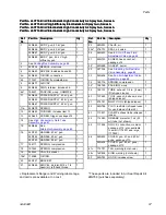
Page 54: ...d spray includes 4a and 4b see Round Spray Assembly page 55 1 4a 24N645 O RING conductive 1 4b 111507 O RING fluoroelastomer 1 24N477 AIR CAP 1 5 24N731 AIR CAP round spray see Round Spray Assembly page 55 1 6 24N644 RING retainer includes 6a 1 6a 198307 PACKING u cup UHMWPE 1 111286 FERRULE front 40 kV gun 1 7 111286 FERRULE front 60 and 85 kV guns 2 111285 FERRULE back 40 kV gun 1 8 111285 FERRU...

Page 55: ...t No No No Description Description Description Qty Qty Qty 24N603 COVER gun 40 and 60 kV guns package of 10 1 46 24N604 COVER gun 85 kV guns package of 10 1 47 179791 TAG warning not shown 1 48 16P802 SIGN warning not shown 1 49 24N730 DIFFUSER for round spray gun only see Round Spray Assembly page 55 1 50 24N783 HOOK includes screw 1 Replacement Danger and Warning labels tags and cards are availa...

Page 56: ...40 kV kV kV High High High Efficiency Efficiency Efficiency Electrostatic Electrostatic Electrostatic Air Air Air Spray Spray Spray Gun Gun Gun Series Series Series A A A Part Part Part No No No L60T16 L60T16 L60T16 60 60 60 kV kV kV Electrostatic Electrostatic Electrostatic High High High Conductivity Conductivity Conductivity Air Air Air Spray Spray Spray Gun Gun Gun Series Series Series A A A P...

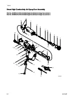
Page 57: ...a 24N979 SPRING 1 12 24N663 TRIGGER includes item 13 1 13 24A445 SCREW trigger package of 2 1 14 See High Conductivity Fluid Tube Assembly page 67 1 15 24N664 See Alternator Assembly page 63 1 24N751 HANDLE 40 kV gun 1 24N752 HANDLE 60 kV gun 1 16 24N753 HANDLE 85 kV gun 1 17 185111 SPRING compression 1 18 197624 SPRING compression 1 19 249323 VALVE exhaust 1 19a 112085 O RING 1 20 24N741 BRACKET ...

Page 58: ... kV Electrostatic Electrostatic Electrostatic High High High Conductivity Conductivity Conductivity Air Air Air Spray Spray Spray Gun Gun Gun Series Series Series A A A Part Part Part No No No L85M16 L85M16 L85M16 85 85 85 kV kV kV Electrostatic Electrostatic Electrostatic High High High Conductivity Conductivity Conductivity Air Air Air Spray Spray Spray Gun Gun Gun Series Series Series A A A 58 ...

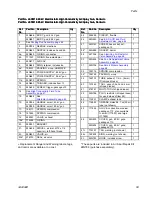
Page 59: ...624 SPRING compression 1 19 249323 VALVE exhaust 1 19a 112085 O RING 1 20 24N741 BRACKET 1 21 24A626 SWIVEL air inlet M12 x 1 4 npsm m left hand thread 1 23 24N633 VALVE air 1 23a 276733 SEAL air valve 1 Ref Ref Ref No No No Part Part Part No No No Description Description Description Qty Qty Qty 24 245265 CIRCUIT flexible 1 26 24N630 See ES On Off and Fluid Adjustment Valve page 64 1 27 24N740 SCR...

Page 60: ...Series Series Series A A A Part Part Part No No No L60M12 L60M12 L60M12 60 60 60 kV kV kV Electrostatic Electrostatic Electrostatic Air Air Air Spray Spray Spray Gun Gun Gun Series Series Series A A A with with with 1 2 1 2 1 2 mm mm mm Nozzle Nozzle Nozzle Part Part Part No No No L85M10 L85M10 L85M10 85 85 85 kV kV kV Electrostatic Electrostatic Electrostatic Air Air Air Spray Spray Spray Gun Gun...

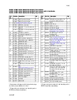
Page 61: ...sembly page 63 1 24N754 HANDLE smart 60 kV gun 1 16 24N755 HANDLE smart 85 kV gun 1 17 185111 SPRING compression 1 18 197624 SPRING compression 1 19 249323 VALVE exhaust 1 19a 112085 O RING 1 20 24N741 BRACKET 1 Ref Ref Ref No No No Part Part Part No No No Description Description Description Qty Qty Qty 21 24N626 SWIVEL air inlet M12 x 1 4 npsm m left hand thread 1 22 24N698 NUT 1 23 24N633 VALVE ...

Page 62: ...escription Description Qty Qty Qty 2a 111316 O RING 1 2b 116905 SEAL 1 2c 178409 PACKING fluid 1 2d 178763 PACKING needle 1 24N701 ROD packing 40 kV guns includes items 2j and 2k 1 24N702 ROD packing 60 kV guns includes items 2j and 2k 1 2e 24N703 ROD packing 85 kV guns includes items 2j and 2k 1 Ref Ref Ref No No No Part Part Part No No No Description Description Description Qty Qty Qty 2f 197641...

Page 63: ...s two bearings item 15e fan and one item 15h clip 1 15d 24N707 HOUSING includes item 15f 1 15e FAN part of item 15b 1 Ref Ref Ref No No No Part Part Part No No No Description Description Description Qty Qty Qty 15f CAP housing part of item 15d 1 15g 110073 O RING 1 15h 24N709 CLIP package of 5 one clip included with item 15b 1 These parts are included in Air Seal Repair Kit 24N789 purchase separat...

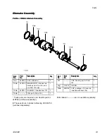
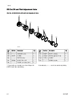
Page 64: ... Part No No No Description Description Description Qty Qty Qty 26a HOUSING valve 1 26b 15D371 O RING 4 26c PISTON valve 1 26f 24N649 LEVER ES on off 1 26g SCREW set socket head 2 Ref Ref Ref No No No Part Part Part No No No Description Description Description Qty Qty Qty 26h 24N631 PLATE retaining 1 26j 24N648 KNOB adjustment fluid 1 26m 113746 O RING 2 26p SCREW captive 1 These parts are included...

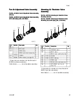
Page 65: ...ed are not available separately Atomizing Atomizing Atomizing Air Air Air Restrictor Restrictor Restrictor Valve Valve Valve Assembly Assembly Assembly Part Part Part No No No 24T304 24T304 24T304 Atomizing Atomizing Atomizing Air Air Air Restrictor Restrictor Restrictor Valve Valve Valve Assembly Assembly Assembly shown shown shown Part Part Part No No No 24N733 24N733 24N733 Atomizing Atomizing ...

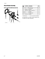
Page 66: ...mbly Assembly Assembly Ref Ref Ref No No No Part Part Part No No No Description Description Description Qty Qty Qty 31a CARTRIDGE 1 31b 24P433 GASKET 1 31c 24N787 SWITCH ES HI LO 1 31d SCREW 3 31e SCREW pivot 1 31f 112319 O RING 1 Parts labeled are not available separately These parts are included in Smart Module Screw Kit 24N757 purchase separately 66 3A2494D ...

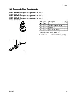
Page 67: ...High High High Conductivity Conductivity Conductivity Fluid Fluid Fluid Tube Tube Tube Assembly Assembly Assembly Includes items 14a 14c Part Part Part No No No 24N629 24N629 24N629 85 85 85 kV kV kV High High High Conductivity Conductivity Conductivity Fluid Fluid Fluid Tube Tube Tube Assembly Assembly Assembly Includes items 14a 14c Ref Ref Ref No No No Part Part Part No No No Description Descri...

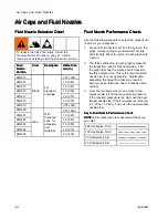
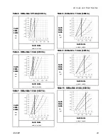
Page 68: ...ing procedure to select the proper fluid nozzle for your application 1 For each fluid nozzle chart find the point on the graph corresponding to your desired flow rate and viscosity Mark the point on each graph with a pencil 2 The thick vertical line in each graph represents the target flow rate for that nozzle size Find the graph that has the marked point closest to the thick vertical line This is...

Page 69: ...in in FLUID FLUID FLUID PRES PRES PRES SURE SURE SURE bar psi FLUID FLUID FLUID FLOW FLOW FLOW oz min cc min Table Table Table 8 8 8 Orifice Orifice Orifice Size Size Size 1 5 1 5 1 5 mm mm mm 0 059 0 059 0 059 in in in FLUID FLUID FLUID PRES PRES PRES SURE SURE SURE bar psi FLUID FLUID FLUID FLOW FLOW FLOW oz min cc min Table Table Table 9 9 9 Orifice Orifice Orifice Size Size Size 1 8 1 8 1 8 mm...

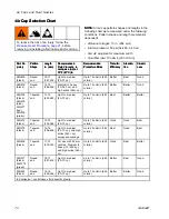
Page 70: ...ciency Efficiency Atomiza Atomiza Atomiza tion tion tion Cleanli Cleanli Cleanli ness ness ness 24N438 black Round end 15 17 381 432 Light to medium 20 70 cp Up to 15 oz min 450 cc min Better Best Good 24N279 black Round end 14 16 356 406 Medium to heavy 70 260 cp and high solids 360 cp Up to 15 oz min 450 cc min Better Better Good 24N376 black 24N276 blue 24N277 red 24N278 green Tapered end 17 19...

Page 71: ...cfm WALL WALL WALL PRESSURE PRESSURE PRESSURE psi Table Table Table 12 12 12 24N376 24N376 24N376 24N276 24N276 24N276 24N277 24N277 24N277 and and and 24N278 24N278 24N278 Air Air Air Caps Caps Caps AIR AIR AIR CON CON CON SUMPTION SUMPTION SUMPTION scfm WALL WALL WALL PRESSURE PRESSURE PRESSURE psi Table Table Table 13 13 13 24N439 24N439 24N439 Air Air Air Cap Cap Cap AIR AIR AIR CON CON CON SU...

Page 72: ... AIR AIR CON CON CON SUMPTION SUMPTION SUMPTION scfm WALL WALL WALL PRESSURE PRESSURE PRESSURE psi Table Table Table 17 17 17 24N453 24N453 24N453 Air Air Air Cap Cap Cap AIR AIR AIR CON CON CON SUMPTION SUMPTION SUMPTION scfm WALL WALL WALL PRESSURE PRESSURE PRESSURE psi Table Table Table 18 18 18 24N477 24N477 24N477 24W279 24W279 24W279 Air Air Air Cap Cap Cap AIR AIR AIR CON CON CON SUMPTION S...

Page 73: ...oz 30 ml 24N318 Round Spray Kit To convert a standard air spray gun to a round spray air cap See manual 3A2498 24N603 Gun Covers For 40 kV and 60 kV guns Box of 10 24N604 Gun Covers For 85 kV guns Box of 10 24N636 Low Profile Atomizing Air Restrictor Valve 24N642 Ball Swivel for gun air inlet 1 4 npsm left hand thread 24N704 Electrode Replacement Needle for Abrasive Materials Blue 24N758 Display C...

Page 74: ...ing gun flush boxes to hold Pro Xp guns 24P312 Gun Washer Kit To convert existing gun washers to clean Pro Xp guns Test Test Test Equipment Equipment Equipment Part Part Part No No No Description Description Description 241079 Megohmmeter 500 V output 0 01 2000 megohms Use for ground continuity and gun resistance tests Not Not Not for for for use use use in in in hazardous hazardous hazardous area...

Page 75: ...5 0 375 in in in 10 10 10 mm mm mm ID ID ID 3 8 3 8 3 8 npsm f npsm f npsm f x x x 1 4 1 4 1 4 npsm f npsm f npsm f left left left hand hand hand thread thread thread 24A225 50 ft 15 m 24A226 75 ft 23 m Part Part Part No No No Description Description Description Grounded Grounded Grounded Air Air Air Hose Hose Hose with with with stainless stainless stainless steel steel steel braid braid braid gr...

Page 76: ...61 20 5 582 L40T16 8 7 221 9 2 234 2 4 61 20 5 582 L60T10 9 5 241 9 2 234 2 4 61 21 1 600 L60T11 8 7 221 9 2 234 2 4 61 21 1 600 L60T12 9 5 241 9 2 234 2 4 61 21 1 600 L60T16 9 5 241 9 2 234 2 4 61 22 6 642 L60M10 9 5 241 10 254 2 4 61 23 7 673 L60M12 9 5 241 10 254 2 4 61 23 7 673 L60M16 9 5 241 10 254 2 4 61 25 4 720 L85T10 10 5 267 9 2 234 2 4 61 23 8 676 L85T16 10 5 267 9 2 234 2 4 61 25 5 725...

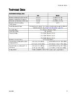
Page 77: ... table of electrostatic results at different resistance levels see Check Fluid Resistivity page 26 Air Inlet Fitting 1 4 npsm m left hand thread Fluid Inlet Fitting 3 8 npsm m Output Voltage Pro Xp40 Models 40 kV Pro Xp60 Models 60 kV Pro Xp85 Models 85 kV Maximum Current Draw 125 microamperes Sound Power measured per ISO Standard 9216 at 40 psi 90 4 dB A at 100 psi 105 4 dB A at 0 28 MPa 2 8 bar ...

Page 78: ...tion for breach of warranty must be brought within two 2 years of the date of sale GRACO GRACO GRACO MAKES MAKES MAKES NO NO NO WARRANTY WARRANTY WARRANTY AND AND AND DISCLAIMS DISCLAIMS DISCLAIMS ALL ALL ALL IMPLIED IMPLIED IMPLIED WARRANTIES WARRANTIES WARRANTIES OF OF OF MERCHANTABILITY MERCHANTABILITY MERCHANTABILITY AND AND AND FITNESS FITNESS FITNESS FOR FOR FOR A A A PARTICULAR PARTICULAR P...

Reviews: