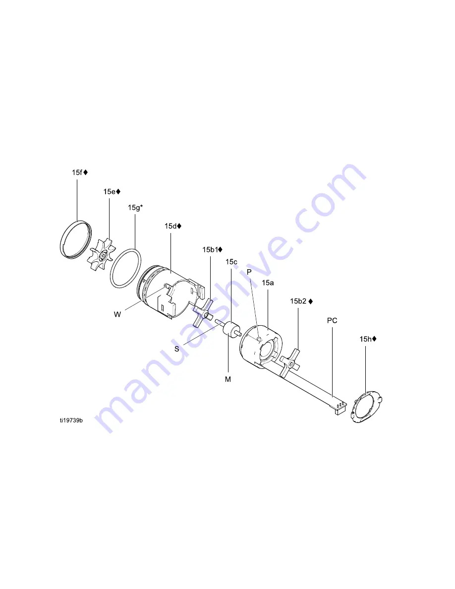
12. Hold the coil assembly (15a) on a workbench
with the fan end facing up. Press the fan (15e♦)
onto the long end of the shaft (S). The fan blades
must be oriented as shown.
13. Carefully press the coil assembly (15a) into the
front of the housing (15d♦) while aligning the
pin on the coil with the slot in the housing. The
3–wire connector (PC) must be positioned below
the wider notch (W) of the housing tabs, as
shown in Figure
. Be
sure the coil alignment pins (P) are positioned as
shown in Figure
.
14. Rotate the fan (15e) so its blades clear the four
bearing tabs (T) at the back of the housing.
Ensure that the blades of the bottom bearing
(15b1♦) align with the tabs.
15. Seat the coil fully into the housing (15d♦). Secure
with the clip (15h♦), ensuring that its tabs engage
the slots in the housing.
16. Ensure that the o-ring (15g) is in place. Install
the cap (15f).
17. Install the alternator on the power supply, and
install both parts in the handle. See
Supply Removal and Replacement, page 56
.
Figure 35 Alternator
58
3A7504A


